
Explore NIST’s Champlain Towers South findings: punching shear, reinforcement details, corrosion, load paths and progressive collapse.
A human tragedy and an engineering question
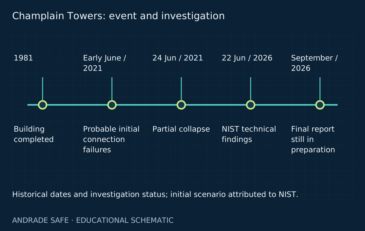
In the early hours of June 24, 2021, part of Champlain Towers South collapsed in Surfside, Florida. Ninety-eight people died. Completed in 1981, the residential building comprised 12 stories, a penthouse and a lower parking level. Any discussion of its structural failure must begin with respect for those lives and their families, without turning destruction into a spectacle.
The engineering question extends beyond identifying the first component that failed. Investigators must explain how a structure that appeared to remain standing lost supports, transferred forces and developed a sequence of failures. Local damage can cross interfaces and affect distant components when alternative load paths cannot provide the required capacity.
This case study explains NIST’s published technical findings and the underlying structural mechanisms. The diagrams are educational and not to scale; they cannot establish the condition of another building through visual resemblance. The purpose is to clarify how design, construction, deterioration and management decisions interact throughout a building’s life.
The 2026 findings are distinct from the final report
On June 22, 2026, the National Institute of Standards and Technology released technical findings on the partial collapse. That is the findings-release date, not the date of the disaster. The official presentation and announcement contain significant conclusions, but should not be described as a published, complete final investigation report.
Our October 9 editorial check included NIST’s September 28 institutional update, revised on October 8. That update described work on topics for recommendations; the complete report and recommendations remained in preparation. This distinction defines what can be stated at publication and leaves room for an update when further official documentation becomes available.
Investigators identified a most probable scenario while acknowledging different propagation sequences consistent with the evidence. Reporting these limits is part of a strong investigation. The technical findings are also separate from legal proceedings: this article does not determine individual responsibility or convert engineering conclusions into a judicial verdict.
Source: NIST technical findings — June 22, 2026 →
Source: NCST activities update — revised October 8, 2026 →
Source: Champlain Towers South investigation hub →
| Layer | Meaning |
|---|---|
| Historical fact | Partial collapse on June 24, 2021; 98 deaths |
| NIST technical finding | Deficiencies and initial punching-shear failures |
| Most probable scenario | Propagation through deck, interface and tower; uncertain details |
| Andrade Safe explanation | Educational mechanics diagrams, not an exact reconstruction |
| Application to Brazil | Technical lessons under Brazil’s own requirements |
Load paths: how forces reach the ground
A structure transfers applied forces to its supports and foundations. In a simplified gravity-load explanation, people, finishes and equipment load the slabs; slabs transfer forces to beams, columns or walls; vertical elements carry those forces toward the foundations and ground. Actual load paths depend on geometry, connection details and the stiffness of each component.
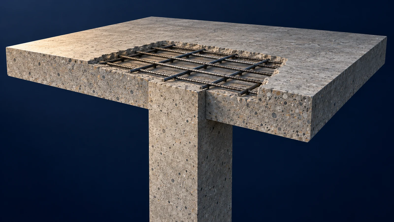
In a flat plate system, a slab can bear directly on columns without a beam at every connection. This makes the slab–column region a particularly important transfer zone. A comparatively small connection participates in supporting a much larger floor area. Edge columns, nearby openings and eccentric force transfer can alter its behavior.
An alternative load path is a route through which some forces can be carried after damage. Simply drawing another route through connected elements does not establish adequate strength. Engineering assessment must examine the transferred demand, the accompanying deformations and whether the receiving connections can continue to perform under those conditions.
Punching shear: a local connection failure
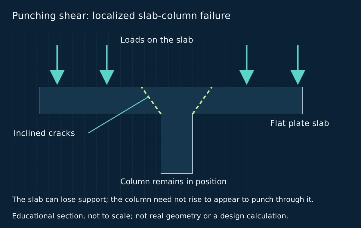
Punching shear is a localized, two-way shear failure around a support or concentrated load. At a slab–column connection, high stresses can produce inclined cracks through the slab thickness. Once the region’s capacity is exceeded, the intended transfer of force through that support can be lost.
The familiar image of a column punching through a slab is useful only if the movement is understood correctly. Under gravity, the slab moves downward relative to the column; the column does not need to rise. The shape and inclination of the failure surface depend on the actual conditions. A cone in a schematic is not a universal fracture shape.
Capacity depends on slab thickness and effective depth, concrete properties, support dimensions, reinforcement, transferred moments, openings and edge conditions. There is no reliable calculation that a resident can complete using a photograph alone. Flexural failure, one-way shear and punching shear are different mechanisms, although they can interact.
Likewise, not every crack indicates punching shear. Shrinkage, temperature changes, deformation and other processes can cause cracking. Professional evaluation considers location, direction, progression and structural context. The absence of a clearly visible crack in an image is not evidence that a connection or building is safe.
Design strength and the reinforcement actually installed
NIST identified original-design deficiencies at particular locations. Some locations had less than half the strength required by the original applicable codes. This is not a finding that the entire building uniformly possessed 50 percent of its required capacity. The conclusion concerns specific regions and checks against the relevant historical requirements.
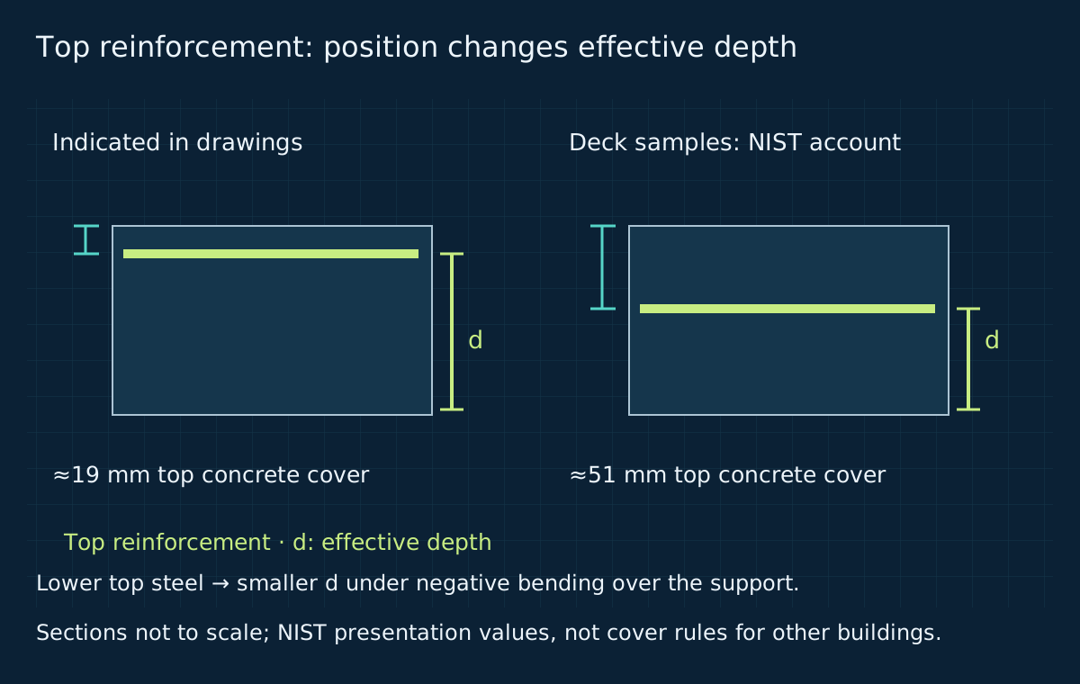
Construction details also mattered. In examined pool-deck specimens, observed top cover was approximately two inches, about 51 mm, compared with three-quarters of an inch, about 19 mm, shown in the drawings. These measurements belong to this investigation; they are not a general recommendation for concrete cover on other projects.
Over a support, negative bending can put the slab’s top face in tension. In that situation, the relevant effective depth runs from the bottom compression region to the center of the top reinforcement. Moving the top steel downward reduces that depth. Greater cover does not automatically increase structural capacity, even though protecting reinforcement from exposure is an important cover function.
Investigators also observed fewer top bars crossing columns than specified and wider spacing in examined regions. Bar quantity, location and continuity influence structural behavior. A neatly finished concrete surface cannot reveal these internal details. Construction control, pre-pour verification and as-built records need to protect the geometry actually required by the design.
Two earlier failures: why did the structure remain standing?
In NIST’s most probable scenario, two connections between garage columns and the pool-deck slab failed in punching shear before the tower collapse: approximately three weeks and one week before June 24. This does not mean that two entire columns visibly fell down weeks earlier. The finding concerns a loss of connection capacity.
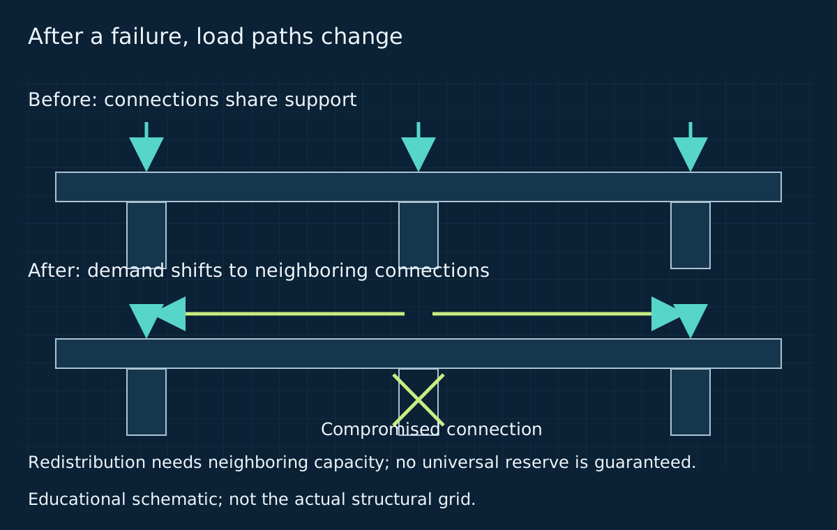
Those failures shifted demand to neighboring regions. Adjacent elements temporarily carried part of the load through mechanisms including bending and compressive membrane action. This helps explain why the system remained standing for a time. It does not establish a safe reserve or a predictable period in which intervention could be completed.
Redistribution can increase forces at connections that are already vulnerable. Deformation changes geometry and how forces travel through a structure. A system that sustains one damaged configuration for some time may fail when further connections give way, demand changes or remaining capacity is exhausted. The observed interval cannot serve as a countdown for another building.
From the pool deck to the tower
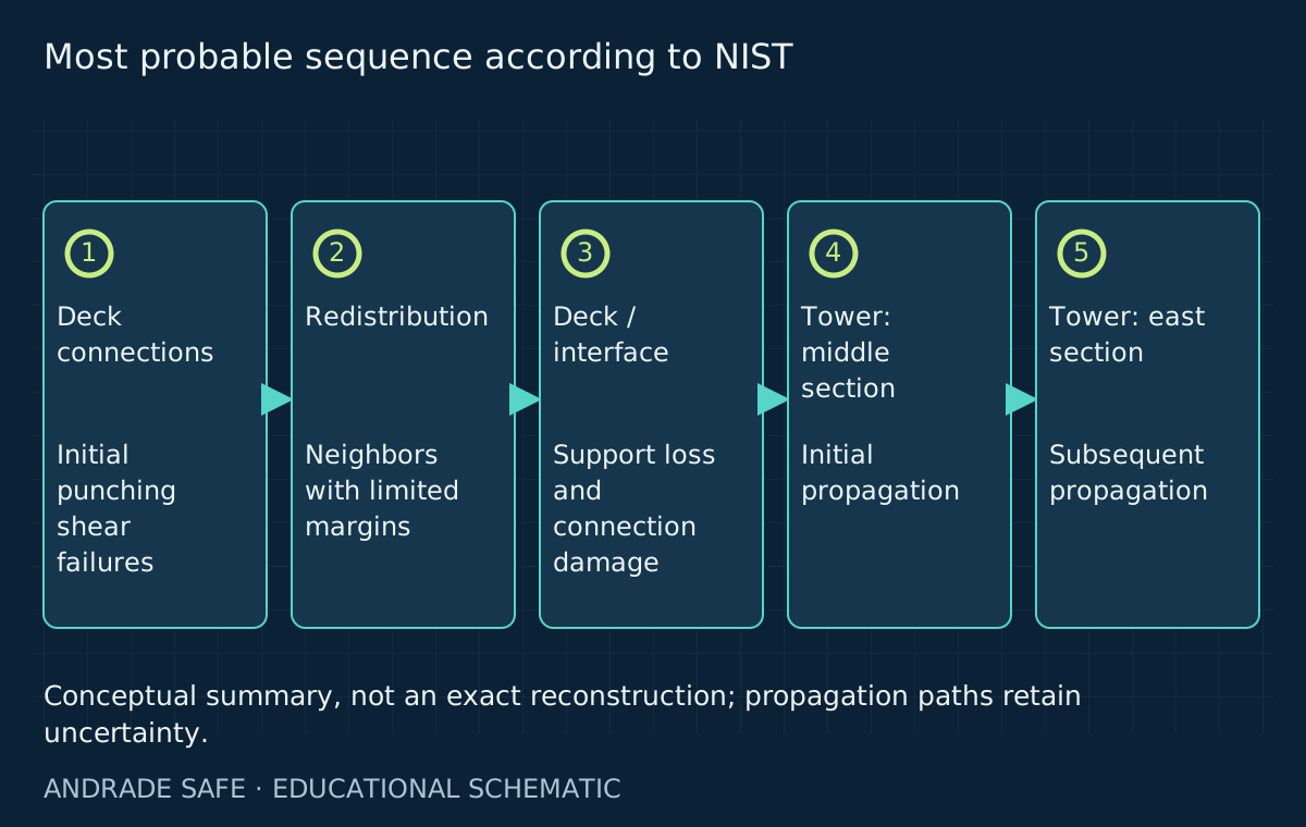
The investigation describes failure progression through the pool deck and associated parking areas. At the southern edge, the deck became unseated from a wall. At the northern edge, separation from the tower damaged two critical slab–beam–column connections in the middle tower section. The interface between building regions became central to understanding the collapse.
Following that damage, failure entered the middle tower section. Its collapse generated actions contributing to the subsequent collapse of the eastern section. The engineering lesson concerns interdependence: a tower’s integrity cannot be evaluated by assuming that an attached area will always behave as an independent structure.
These events form the most probable explanation supported by the published evidence. More than one propagation sequence was compatible with the analyses. Our illustrations therefore do not assign exact seconds, verified dimensions or a complete forensic reconstruction. They show relationships between supports, interfaces and force transfer.
Nor does the explanation imply that every slab collapse inevitably spreads into a tower. Consequences depend on the structural system, the connection type, available capacity and the form of damage. A building-specific analysis must demonstrate those relationships rather than import the sequence from another case.
Progressive collapse, redundancy and robustness
Progressive collapse describes the spread of failures from an initial damaged region into a larger part of a structure. It is not another name for every piece of falling concrete or every isolated element failure. Engineers examine the relationship between the initial loss and the eventual extent of the consequences.
Redundancy concerns the availability of components or paths that can share structural functions. Robustness concerns the system’s ability to limit disproportionate consequences under damage or adverse conditions. These concepts are related but distinct. Many apparent supports do not establish robustness if their connections share similar vulnerabilities.
Connections also need behavior compatible with the deformation required after damage. Adding together isolated component strengths does not demonstrate that all that capacity can be mobilized at once. Support loss can introduce dynamic effects, altered restraints and redistributed moments, making the behavior of the assembled system essential.
Remaining upright for a period is therefore an observation to interpret, not a certificate of stability. None of the diagrams or descriptions in this article should determine occupancy, evacuation restrictions or shoring arrangements for an actual property. Those decisions require a competent, site-specific structural assessment.
Water, corrosion and additional loads
Reinforced concrete relies on concrete and steel working together. Under adverse conditions, water and aggressive agents can contribute to reinforcement corrosion. Chlorides in marine environments are a recognized concern, but actual deterioration depends on exposure, materials, protection and the structure’s history. A coastal address alone cannot quantify damage.
Corrosion may reduce steel cross-sectional area. Corrosion products can also expand, crack or detach concrete and impair bond between reinforcement and concrete. These mechanisms explain how strength and durability may deteriorate; they do not independently determine the remaining capacity of a particular slab–column connection.
For Champlain Towers, NIST treated corrosion and changes in loading as contributors within a structure affected by design and construction deficiencies. Reducing the explanation to rust erases that combination. Conversely, recognizing original shortcomings does not make leakage, waterproofing or maintenance irrelevant to structural integrity.
Finishes, equipment, storage and changes of use can modify loads. Before a renovation, the proposed removals, additions and penetrations need to be understood alongside the elements they affect. A garage slab or outdoor deck remains part of the structure; engineering significance does not depend on being inside an apartment.
Observable symptoms are not a structural diagnosis
Persistent leakage, spalling concrete, exposed reinforcement, deformation and developing cracks deserve evaluation appropriate to their context. A useful record describes the location, when a condition was noticed and how it changed. Such documentation assists the professional; it does not make the observer responsible for deciding structural stability.
No visual checklist reliably separates every cosmetic issue from a structural risk. A small crack at a critical location can differ in significance from a larger crack in a finish. Measuring width in isolation or comparing online images may create either unnecessary alarm or false reassurance. Context and evolution matter alongside appearance.
When there is an indication of risk, avoid exposure to the affected area, notify building management and obtain assessment by a qualified structural engineer. Area restrictions and contact with authorities should reflect the severity and competent instructions. Do not enter a suspect area simply to obtain a better photograph or test whether concrete is loose.
Shoring, load removal and repairs are engineering decisions: a poorly planned intervention can itself change forces. This article does not prescribe improvised fixes. Proper assessment establishes urgency, access conditions, necessary investigation and protective measures, with clear responsibilities and records that explain why each decision was taken.
- New or developing symptoms and unusual deformation: seek assessment appropriate to urgency.
- Corrosion with suspected section loss: investigate extent and impact without estimating strength from images.
- Changed use or loading and undocumented works: assess actual conditions and recover records.
- Inconclusive reports or suspected changes to columns, beams or slabs: establish a specialist investigation.
How forensic engineering tests an explanation
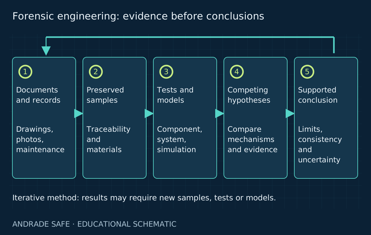
An investigation combines design drawings, construction and renovation records, maintenance documents, witness accounts, photographs, videos and physical evidence. Every source has limits. A drawing records intent; a sample describes a particular region; a video captures a view and a time interval. Conclusions must explain how these different forms of evidence fit together.
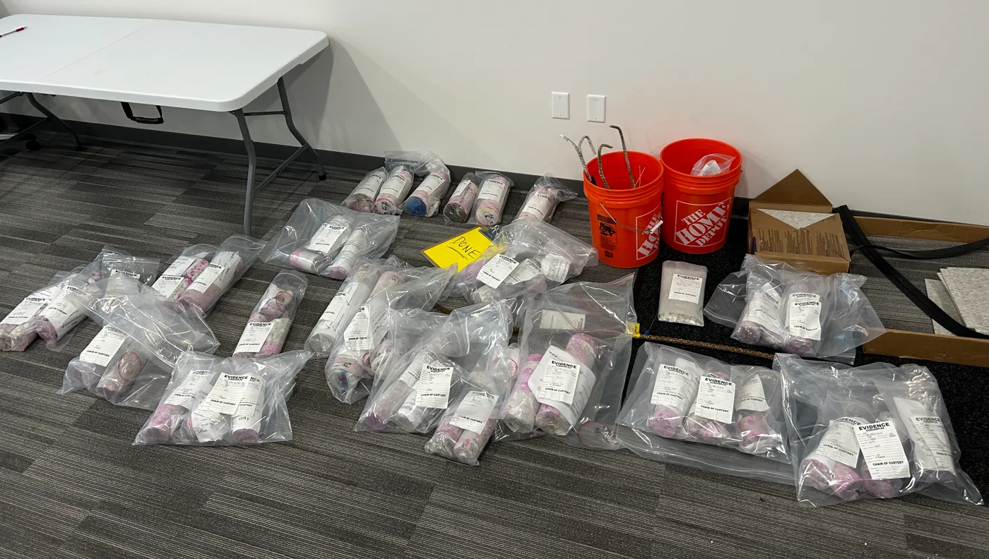
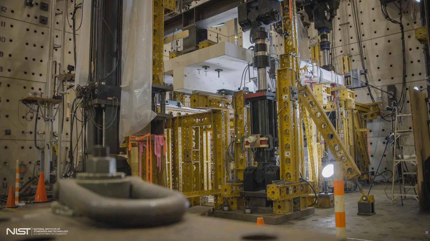
Preservation and traceability help distinguish physical evidence from later interpretation. Testing can characterize concrete, steel and connections. Full-scale replicas allow mechanisms to be observed under controlled conditions. The official photographs included here show a laboratory replica and material samples, not the actual moment of collapse or an operating building.
Computational models allow investigators to compare hypotheses and explore behavior that cannot be observed directly. They require assumptions, material properties, support conditions and validation criteria. A compelling animation is not a substitute for agreement with evidence. Uncertainty must be examined rather than concealed by the apparent precision of a numerical output.
NIST evaluated roughly two dozen scenarios. It ruled out foundation failure and subsidence or sinkholes, neighboring construction vibration, storms, impulsive crane or explosion forces, and accidental overload associated with the roof project as initiating causes. Rejected explanations should not be presented as equally supported alternatives without new evidence.
Source: Technical findings: official transcript →
Source: Full-scale specimen before testing — January 2025 →
Official videos: overview and technical presentation
NIST offers a short summary and an extended technical presentation. The summary introduces the two initial connection failures and subsequent load transfer. The longer presentation lets readers follow the investigators’ explanation and compare it with the official transcript, particularly the discussions of design strength, reinforcement and propagation.
Both videos are in English and represent the June 2026 technical disclosure. Viewing them does not change the status of the final report. A gallery upload date should not be confused with the public release date or with the 2021 collapse. Official page links accompany the players so readers can consult the original context directly.
NIST — Summary of Technical Findings (June 2026)
Official NIST video in English. Technical findings disclosure, not a published final report. Use the official link if the player is unavailable.
NIST — Technical Findings (June 2026)
Official NIST video in English. Technical findings disclosure, not a published final report. Use the official link if the player is unavailable.
Lessons for Brazil under Brazilian standards
The collapse occurred in the United States and was investigated in its historical and regulatory context. Brazilian standards should not be applied retroactively to declare compliance or violation at that building. A useful comparison concerns prevention, documentation and professional assessment for existing structures in Brazil, without transplanting legal conclusions.
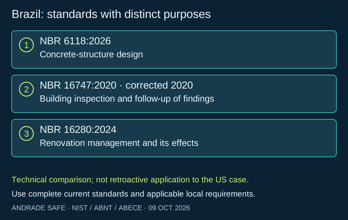
In the October 2026 check, ABNT’s catalog lists NBR 6118:2026 for concrete-structure design. ABECE explains that it consolidates NBR 6118:2023 with Amendment 1 from March 2026. NBR 16747:2020, with its 2020 corrected version, addresses building inspection; NBR 16280:2024 addresses renovation management. Their scopes differ and complement one another.
Building inspection provides an organized assessment, but findings may require a specialist structural investigation. Renovation management controls interventions and their effects; it does not replace necessary structural design. Design, inspection and renovation must connect with maintenance, professional responsibilities and applicable local requirements. Their technical purposes should remain clear.
This article sets no universal inspection interval and reproduces no isolated clauses as blanket obligations. Frequency and assessment depth depend on the building, exposure, history and relevant requirements. The responsible professional needs the complete current documents and must record the scope, limitations and follow-up of findings rather than assume a general visit answers every structural question.
Source: ABNT catalog — NBR 6118:2026 →
Source: NBR 6118 amendment and consolidated 2026 edition →
Source: NBR 16747 corrected version — current catalog entry →
Source: NBR 16280:2024 — current catalog entry →
Source: Publication and purpose of NBR 16747 →
| Brazilian reference | Purpose | Comparison limit |
|---|---|---|
| NBR 6118:2026 | Concrete-structure design | Not applied retroactively to the US case |
| NBR 16747:2020, 2020 corrected version | Building inspection | May require specialist structural investigation |
| NBR 16280:2024 | Renovation management | Does not replace necessary structural assessment and design |
Prevention through verifiable barriers
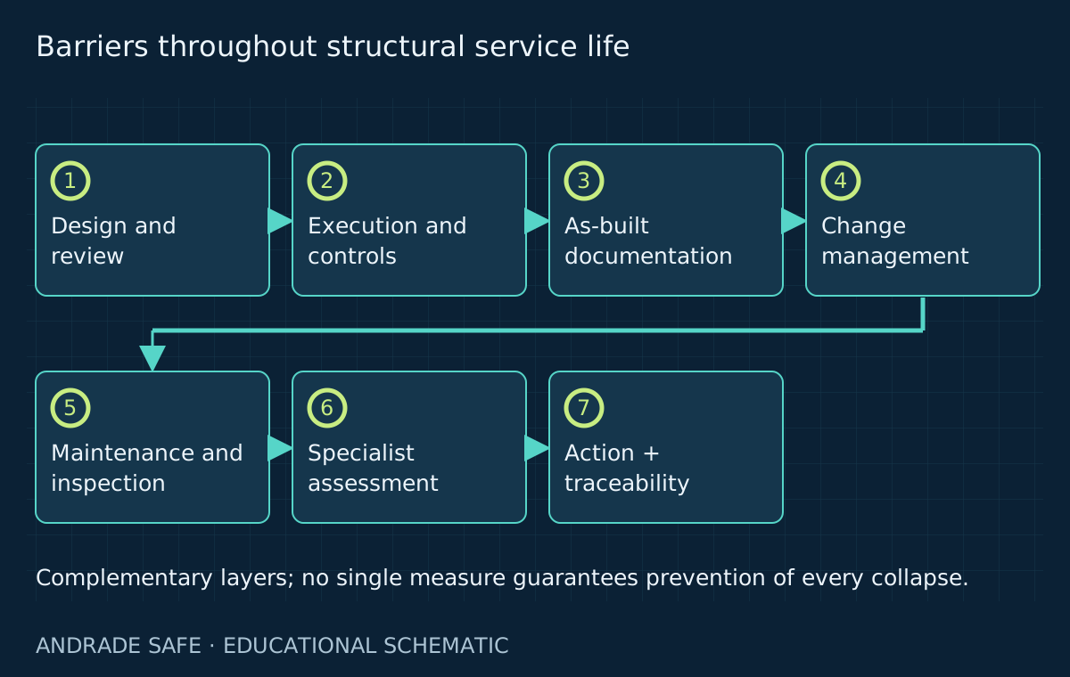
Prevention begins with explicit load assumptions, connection checks and an independent design review appropriate to the project. It continues during construction: reinforcement position, supports, dimensions, concrete placement and deviations must be checked before they become hidden. As-built records retain information needed for future assessment and make changes traceable.
During use, waterproofing, drainage and maintenance require observation and a documented response. Closing a work order does not establish that the underlying cause of leakage has been removed. The result needs verification, recurrence needs attention, and some problems require investigation beyond a superficial repair. Maintenance records should help reveal that distinction.
Renovations require assessment of their effects on loads and structural components. Inspections need to produce priorities, assigned responsibilities, deadlines and completion criteria. Recommendations that remain filed away do not operate as a barrier. Management has to track implementation and evaluate whether the specified action actually addresses the finding.
No single measure here establishes that it would have prevented Champlain Towers. The transferable lesson is the value of independent, traceable barriers that can identify and address problems at different stages. A sequence of technically informed decisions creates opportunities to control deficiencies before they accumulate or interact in ways the original system cannot sustain.
Understand the system and act on the findings
Champlain Towers illustrates why a deck, a connection and a few centimeters of reinforcement position can matter to an entire structural system. It also shows the need to distinguish established findings, the most probable sequence and educational explanation. Responsible engineering makes those distinctions visible instead of overstating certainty.
Other case studies on this blog examine accident-investigation methods, risk governance, tunnel emergencies and seismic risk in mining. Their physical mechanisms differ. Their shared value lies in preserving evidence, understanding interfaces, assigning technical responsibility and translating knowledge into actions whose completion is tracked, with respect for the people affected.
Nepal tunnel rescue: engineering decisions in an emergency →
Frequently asked questions
What caused the collapse according to NIST?
The most probable scenario begins with punching-shear failures at two pool-deck slab–column connections. Loads shifted to vulnerable regions, and deck separation damaged critical tower connections. Design and construction deficiencies, corrosion and loading changes formed part of the explanation. This is not a single-cause account or a determination of individual legal responsibility.
When did the collapse occur and when were findings released?
The partial collapse occurred on June 24, 2021. NIST released technical findings on June 22, 2026. At the October 2026 editorial check, the complete final report and recommendations remained in preparation. The event, technical disclosure and final report are separate milestones.
What is punching shear in a slab?
It is a localized, two-way shear failure around a support or concentrated load. At a slab–column connection, the region can lose its intended capacity to transfer forces. Under gravity, the slab moves down relative to the column; the column does not need to rise or actively drive through it.
Does every crack indicate structural failure?
No. Cracks have different possible origins, including effects limited to finishes. Their location, development and context require professional interpretation. Equally, an absence of visible cracks in a photograph does not establish safety. Visual comparison with Champlain Towers cannot replace assessment of a particular property.
What does progressive collapse mean?
It describes failure spreading from an initial damaged region into a larger part of a structure. Connections, alternative paths, capacity and deformation influence the extent. It is not inevitable after every defect, but the consequences of losing a support require attention when other components may be affected.
Was corrosion the only cause?
No. NIST described original deficiencies and construction deviations, with corrosion and loading changes contributing. General deterioration mechanisms help explain structural vulnerability but do not attribute the entire sequence to one leak or establish residual capacity from an image. The combination of conditions is central to the findings.
How could the pool deck affect the tower?
The regions interacted through supports and connections. In the most probable scenario, deck separation damaged two critical connections in the middle section and allowed failure to enter the tower. This illustrates the importance of interfaces without establishing identical behavior for every deck attached to another building.
Why does top reinforcement position matter?
Under negative bending over a support, top reinforcement participates in resisting tension. Its position affects effective depth relative to the bottom compression region. In the examined specimens, greater top cover reduced that distance. The effect is situation-specific; these measurements are not a universal concrete-cover rule.
How are investigation hypotheses tested?
Investigators combine records, accounts, visual documentation and physical evidence, characterize materials, test replicas and compare models with observations. Traceability and examination of alternative scenarios help assess explanations. Simulations require assumptions and validation; their visual realism alone cannot establish whether a proposed sequence occurred.
When should a structural engineer be consulted?
Seek specialist assessment for potentially structural damage, deformation or changing cracks, and before work that affects structural components or loads. Where risk is indicated, avoid exposure, notify management and seek competent guidance and authority involvement according to severity. Urgency and occupancy decisions require a site-specific assessment.
References
- NIST technical findings — June 22, 2026NIST
- Technical findings: official transcriptNIST
- NCST activities update — revised October 8, 2026NIST
- Champlain Towers South investigation hubNIST
- Summary of technical findings — official videoNIST
- Technical findings — official videoNIST
- Full-scale specimen before testing — January 2025NIST
- Concrete cores and reinforcing steel — July 2023NIST
- Copyrights and image reuse policyNIST
- ABNT catalog — NBR 6118:2026ABNT
- NBR 6118 amendment and consolidated 2026 editionABECE
- NBR 16747 corrected version — current catalog entryDIN Media / ABNT
- NBR 16280:2024 — current catalog entryDIN Media / ABNT
- Publication and purpose of NBR 16747CBIC