
Learn how an air conditioner uses 1 kW of electricity to remove 3.5 kW of heat. Explore the refrigeration cycle, COP, worked examples and a calculator.
A calculation that looks impossible—until we choose the right system
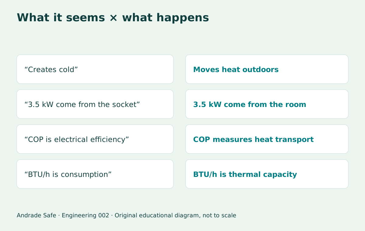
If an air conditioner draws 1 kW of electrical power, how can it remove 3.5 kW of heat from a room? The question seems to describe a machine delivering more energy than it receives. But one input is missing from that calculation: the thermal energy already present indoors. The electrical supply provides the work needed to transfer that energy outdoors.
The appliance does not manufacture a substance called cold. It maintains a circuit that absorbs heat on one side and rejects it on the other. In Engineering series edition 002, we will follow that circuit, solve two exercises and explore a COP calculator. The value 3.5 is an educational performance assumption, not a promise for every model or climate.
Heat, temperature and power: three different concepts
Temperature describes a thermal state; heat is energy transferred because of a temperature difference. A room can gain energy from sunlight, walls, people, computers and incoming air. To lower or maintain its temperature, refrigeration must handle those gains and the energy stored in surrounding materials. The space is more complicated than a box containing only air.
The watt measures a rate of energy transfer: 1 kW is 1,000 joules per second. The kWh measures energy accumulated over time. If electrical power remains at 1 kW for one hour, consumption is 1 kWh. If heat removal remains at 3.5 kW over the same interval, the thermal energy removed is 3.5 kWh. These quantities have the same energy dimension, but different origins and destinations.
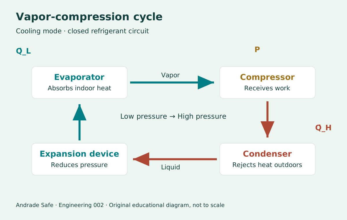
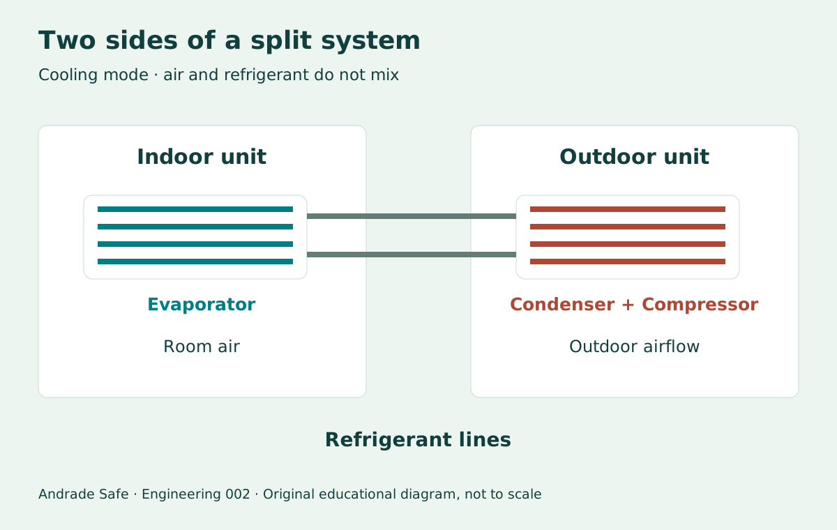
The everyday phrase “making cold” describes a sensation, not the physical energy balance. The indoor coil becomes cold enough to absorb heat from the air. Refrigerant circulates inside tubes; room air passes outside those tubes and returns to the room. In an ordinary split system, that air does not need to travel to the outdoor unit.
The four components of the vapor-compression cycle
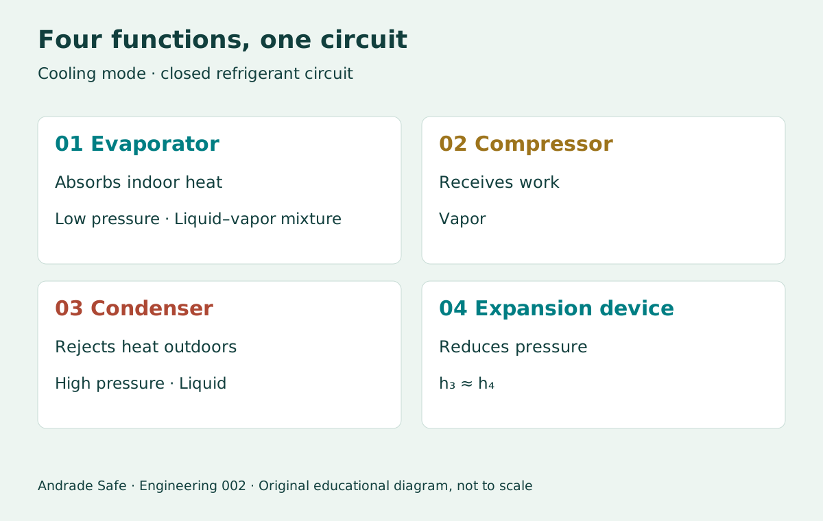
The evaporator receives refrigerant at low pressure. In a conventional cycle, much of the heat absorption occurs as it vaporizes. The fluid leaves as vapor, normally with some superheat to protect the compressor. The indoor fan promotes heat transfer between the air and the coil; it does not create the refrigerant’s low temperature.
The compressor receives vapor and supplies work to the fluid, raising its pressure and temperature. In the condenser, the hot refrigerant then rejects heat to the outdoor surroundings, changing from vapor to liquid over part of its path. The outdoors can be warmer than the room and still receive heat because the refrigerant in the condenser is hotter than the outdoor air.
The expansion device restricts the flow and reduces pressure. For approximately adiabatic throttling, with no work and negligible changes in kinetic and potential energy, enthalpy remains approximately constant: h₃ ≈ h₄. Some liquid vaporizes, and the mixture returns to the evaporator. This device is not a miniature turbine producing work; nor should the temperature drop be explained only through the ideal gas law.
The cycle repeats in a closed circuit. Component functions depend on operating mode: in a reversible appliance operating in heating mode, the indoor coil acts as a condenser. The diagrams in this article show indoor and outdoor locations for cooling mode.
Source: CYCLE_D-HX — Technical Note 2134 →
| Component | What happens to the refrigerant | Main interaction |
|---|---|---|
| Evaporator | Low pressure; heat absorption and vaporization | Heat enters the circuit |
| Compressor | Vapor compression; pressure and temperature increase | Work enters the circuit |
| Condenser | Heat rejection; condensation | Heat leaves the circuit |
| Expansion device | Pressure drop; liquid–vapor mixture | No useful work in the idealized model |
The First Law: where does the energy go?
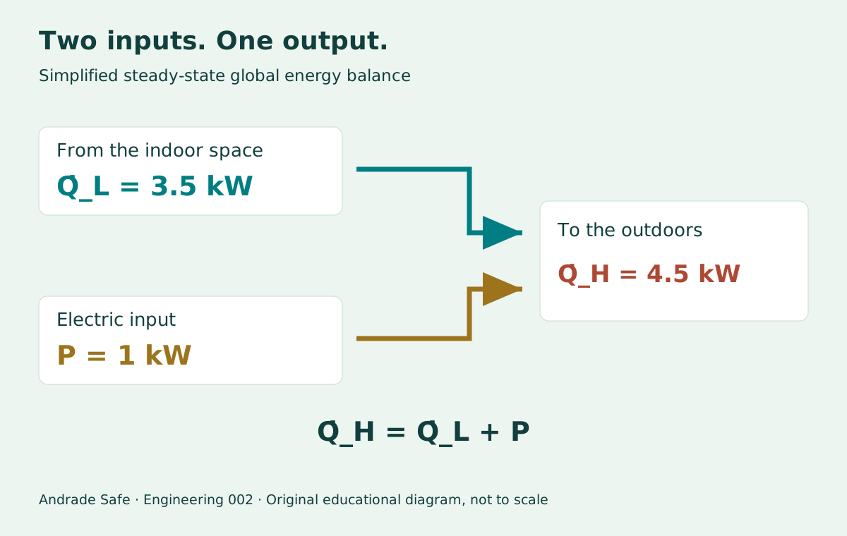
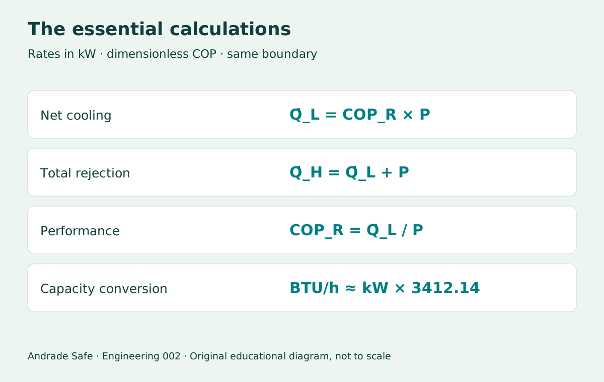
For a steady-state cycle, neglecting losses to other destinations and changes in kinetic and potential energy, the balance is Q̇_H = Q̇_L + P. Q̇_L is the rate of heat absorbed on the cold side; Q̇_H is the rate rejected on the hot side; P is the power entering the system. The dot over Q denotes a rate. Without the dot, Q usually represents energy, in joules or kWh; W usually represents work, not power.
The chosen system boundary matters. In a refrigerant-circuit model, P is the work actually supplied to the fluid by the compressor. When assessing the complete appliance electrically, the motor, electronics and fans also count. For the example and calculator, we use total electrical power and net cooling capacity removed from the room, assuming that all this electrical input ultimately becomes heat outdoors. This assumption closes the overall balance without implying that all electrical energy reaches the refrigerant as shaft work.
The example’s 4.5 kW therefore represents total heat rejection outdoors within the adopted model. Heat transferred through the condenser coil alone can differ from that total, depending on motor losses, fan locations and the definition of measured capacity. The simplification is useful provided that calculation boundaries and test boundaries are not mixed.
Source: Applications of Thermodynamics: Heat Pumps and Refrigerators →
COP: how much heat can we move per unit of power?
The refrigeration coefficient of performance is COP_R = Q̇_L / P. When both rates are expressed in kW, their units cancel. A COP of 3.5 means removing 3.5 units of thermal energy from the cold side for each unit of electrical energy consumed, under the stated conditions and system boundary.
This is not equivalent to converting electricity into newly created energy with an efficiency of 350%. The useful function is to transport heat that already exists, rather than to convert the electrical input alone into useful output. COP measures this transport task; motor efficiency measures a different task. Comparing the two as though they were the same ratio conceals the thermal input from the surroundings.
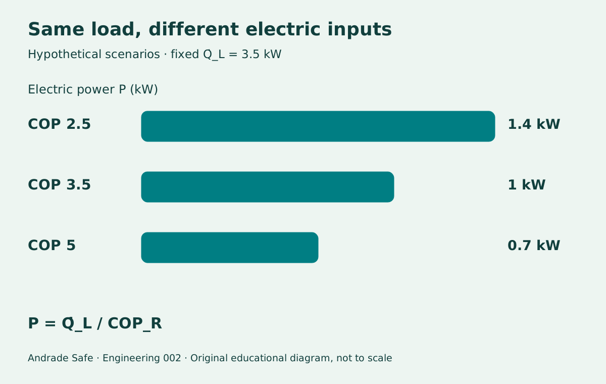
For a fixed cooling load of 3.5 kW, P = Q̇_L / COP_R. At COP 2.5, calculated power is 1.4 kW; at COP 3.5, it is 1.0 kW; at COP 5.0, it is 0.7 kW. This is a mathematical comparison of scenarios, not a product test. To compare real appliances, keep test conditions the same and check which electrical loads are included.
Worked example: 1 kW electrical, 3.5 kW removed, 4.5 kW rejected
Problem: a system operates at total electrical power P = 1.0 kW with a refrigeration COP of 3.5. What is its net cooling capacity for the room? What is its total heat rejection outdoors? Assume steady-state operation and the simplified overall system boundary defined above.
Step 1—apply the COP definition: Q̇_L = COP_R × P = 3.5 × 1.0 = 3.5 kW. That heat comes from the cooled space; it does not originate at the electrical outlet. Step 2—apply conservation of energy: Q̇_H = Q̇_L + P = 3.5 + 1.0 = 4.5 kW. The outdoors receives both the energy removed from the room and the electrical energy consumed.
Step 3—interpret one hour of constant operation: 1.0 kWh of electricity and 3.5 kWh of thermal energy enter, while 4.5 kWh of thermal energy leave. There is no surplus or deficit. This also explains why air discharged by an outdoor unit can heat a poorly ventilated balcony: the rejected heat needs somewhere to go.
| Quantity | Rate | Energy in 1 hour |
|---|---|---|
| Electrical input P | 1.0 kW | 1.0 kWh |
| Net heat removed Q̇_L | 3.5 kW | 3.5 kWh |
| Total heat rejected Q̇_H | 4.5 kW | 4.5 kWh |
Laboratory: change the power input and COP
Use the two fields below to investigate the energy balance. Changing COP at fixed power changes calculated cooling capacity; changing power at fixed COP increases all rates proportionally. The inputs are assumptions supplied by the reader: the calculator does not predict a product’s COP or check the thermodynamic limit at specified temperatures.
The result in BTU/h describes only the heat removed. The diagram follows the values and distinguishes the two incoming flows from the outgoing flow. Empty fields, negative values, zero and nonfinite values produce no results. The displayed precision helps you follow the arithmetic; it does not characterize a measurement.
Explore the energy balance
Change the inputs to follow two incoming energy flows and one outgoing flow. Calculations run in your browser.
- Net heat removed Q̇_L (kW)
- 3.50
- Total heat rejected Q̇_H (kW)
- 4.50
- Cooling capacity (BTU/h)
- 11,942
From the indoor space: 3.50 kW
Electricity: 1.00 kW
To the outdoors: 4.50 kW
3.50 + 1.00 = 4.50 kW
Educational steady-state estimate using net cooling and total electric input; all electric input ultimately becomes heat outdoors. Total rejection may differ from heat passing through the condenser coil alone. This does not predict COP, check temperatures or size equipment.
BTU/h, refrigeration tons and a second worked example
BTU is a unit of energy; BTU/h is an energy rate and therefore a measure of cooling capacity. Using the International Table BTU, 1 kW ≈ 3,412.14 BTU/h. Thus, 3.5 kW corresponds to approximately 11,942 BTU/h. One refrigeration ton, or TR, equals 12,000 BTU/h ≈ 3.517 kW. The word ton here does not refer to the appliance’s weight.
Example 2: assume a cooling capacity of 12,000 BTU/h and total electrical power of 1.1 kW, both measured under the same operating condition. Convert the capacity: Q̇_L = 12,000 / 3,412.14 ≈ 3.517 kW. Then COP_R = 3.517 / 1.1 ≈ 3.20. Under the simplified overall balance, heat rejection would be approximately 4.617 kW.
Do not conclude that a 12,000 BTU/h appliance consumes 3.517 kW of electrical power. That number describes its thermal capacity. Electrical power depends on performance, controls and conditions. Nor should a nominal capacity be divided by instantaneous power measured under a different condition and the resulting ratio called nominal COP.
EER and IDRS: reading a label without mixing metrics
EER expressed in BTU/(W·h), also written Btu/Wh, is cooling capacity in BTU/h divided by power in watts. For the same data and conditions, EER ≈ 3.41214 × COP_R. Thus COP 3.5 corresponds to EER ≈ 11.94 Btu/Wh. Some documents express EER in W/W; in that case, its numerical value equals refrigeration COP when the test definitions agree. The unit must accompany the number.
Seasonal performance combines operating conditions and loads over a usage profile rather than describing a single operating point. In Brazil, the Inmetro label uses the Seasonal Cooling Performance Index, known by the Portuguese acronym IDRS, and gives standardized annual consumption. IDRS should not be treated as the instantaneous COP in our exercise or automatically converted using the relationship for EER in Btu/Wh.
The annual consumption on the label provides a standardized comparison; it does not predict your household bill exactly. Operating hours, climate, solar gains, insulation, occupancy and temperature settings change the outcome. To compare appliances in the Brazilian market, consult Inmetro’s PBE system and compare capacity and performance metrics under the same assessment procedure.
Source: Nova etiqueta para condicionadores de ar →
Source: Sistema PBE para consulta dos produtos etiquetados →
The Second Law: why can COP not increase without limit?
The First Law balances the energy account. The Second Law limits which processes can achieve that balance. Heat flows spontaneously from hotter to colder surroundings; sustaining transfer in the opposite direction requires compensation, supplied here through work. Each local heat exchange still follows its temperature gradient: indoor air warms the cold evaporator, and the hot condenser warms outdoor air.
For an ideal reversible refrigerator operating between two reservoirs at constant temperatures, the limit is COP_R,Carnot = T_L / (T_H − T_L), using absolute temperatures in kelvin. Our theoretical example, T_L = 280 K and T_H = 315 K, gives a maximum COP of 8. This does not predict a split system’s performance: real compression, throttling, finite temperature differences and losses introduce irreversibilities.
The larger the difference between the evaporation and condensation temperature levels, the more demanding operation tends to become. Do not use the remote-control setpoint and weather temperature directly as though they were the refrigerant temperatures in the heat exchangers. Heat transfer requires temperature differences, and superheat, subcooling and pressure drops also matter. The Carnot ceiling is a fundamental reference, not a commercial performance label.
Real COP depends on climate, maintenance, controls and load
High outdoor temperature makes heat rejection more difficult. Blocked filters and dirty coils impair airflow and heat transfer; an outdoor unit installed in an unsuitable space may recirculate hot air. The result depends on the system and its operation, so no universal energy-saving percentage can be assigned to cleaning or to an isolated adjustment.
Inverter control allows compressor speed to vary and capacity to match demand within the operating range. It can avoid some losses associated with on/off cycling and improve part-load performance. But the word inverter alone does not define COP: installation, load range, test conditions and auxiliary consumption remain important.
Total cooling capacity includes sensible capacity, which lowers temperature, and latent capacity, associated with moisture removal through condensation. In a humid climate, some of the useful effect does not appear as a direct drop in air temperature. Drain water comes from moisture in the air; it should not be confused with a refrigerant leak.
To estimate energy consumption at constant power, E_el = P × t. At 1 kW for 8 hours, consumption would be 8 kWh; at a hypothetical Brazilian tariff of R$1.00/kWh, the cost would be R$8.00. In practice, power varies: consumption must be integrated or measured over the period. COP does not replace cooling-load calculation, capacity selection or installation checks.
Source: Field Validation of Air-Source Heat Pumps for Cold Climates 2021–2023 →
From refrigerators to heat pumps: the same physics, different objectives
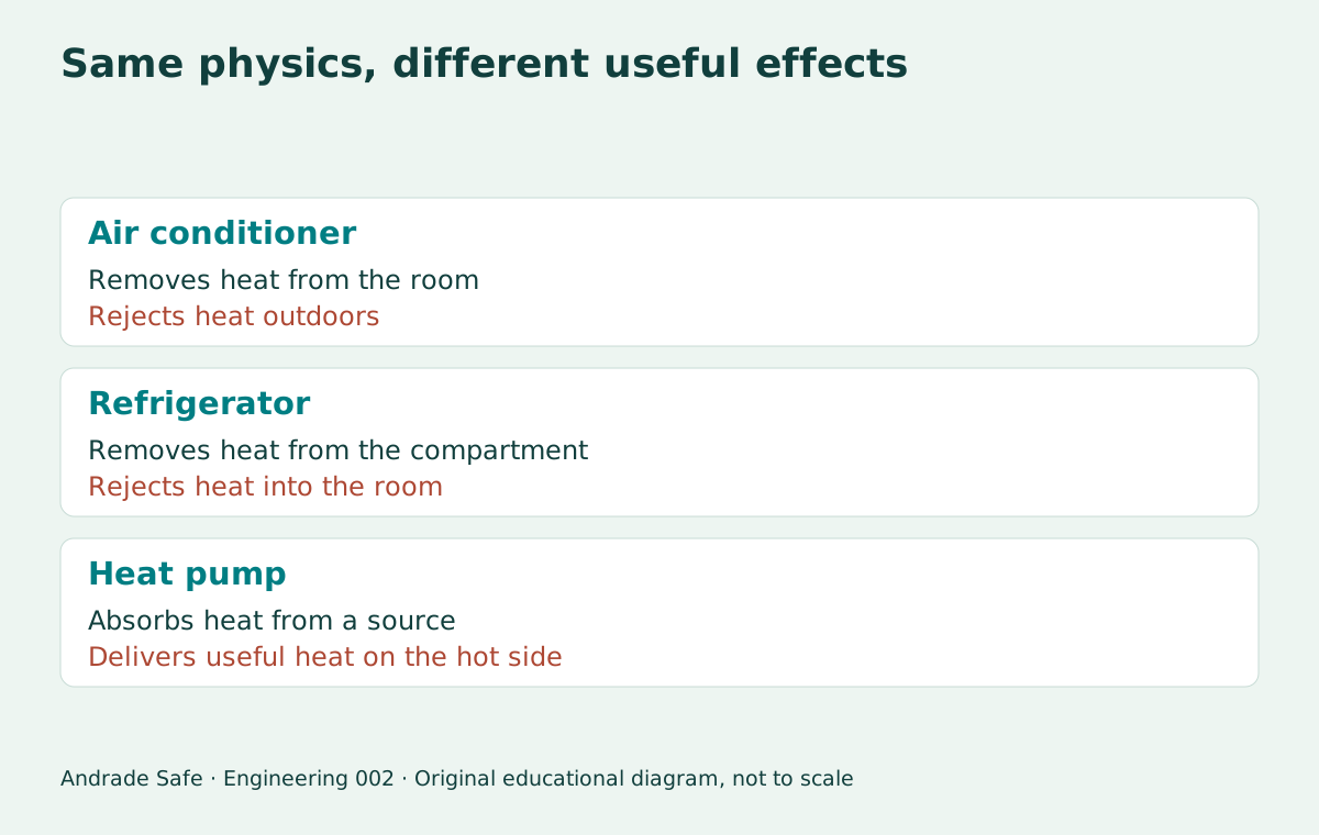
A refrigerator removes heat from a compartment; an air conditioner removes it from an occupied space; a cold room removes it from products and storage space. A heat pump in heating mode uses the heat rejected on the hot side as its useful effect. For the same cycle and system boundary, COP_H = Q̇_H / P = COP_R + 1. In our example, the hot side would deliver 4.5 kW for 1 kW of input, but this does not predict performance after switching operating modes or temperatures.
Leaving a refrigerator door open does not cool a room the way a split system does. The heat removed is returned to the same room, together with the consumed electrical energy, producing net heating in the overall balance. Engineering solves this by separating the locations of heat absorption and heat rejection and planning ventilation, heat exchangers and controls.
In buildings and industrial processes, understanding these flows helps us consider insulation, heat recovery, equipment cooling and energy consumption. The previous edition in this series showed how pipe diameter affects head loss and pumping. Here the reasoning is similar: define the system, track the units and interpret the result before making a decision.
An air conditioner seems paradoxical only until we understand its actual task: using work to transport heat. Its appeal lies in organizing fluid properties, pressure and heat transfer into a cycle that makes comfort possible. Once we see the two inputs and one output, 3.5 stops looking like magic and becomes a coherent engineering story.
Frequently asked questions
Does an air conditioner create cold?
It removes thermal energy from a room and transfers it outdoors. The sensation of cold results from lower temperature and comfort conditions, but cold is not created as an energy flow. In cooling mode, the evaporator absorbs heat and the condenser rejects it.
What is COP in air conditioning?
It is the ratio of cooling capacity to power consumed, using the same system boundary and operating conditions. COP 3.5 means 3.5 kW of heat removed for 1 kW of electrical input in our example. The coefficient is dimensionless; actual values depend on operation and the test definition.
How do you calculate the heat removed?
Multiply power by the performance ratio: Q̇_L = COP_R × P. With 1 kW and COP 3.5, cooling capacity is 3.5 kW. Accumulated energy also depends on time and changes in those rates. An instantaneous power value alone does not describe monthly consumption.
Why is heat rejection greater than the heat removed?
In the simplified overall balance, the consumed electrical energy also ultimately becomes heat outdoors. Therefore Q̇_H = Q̇_L + P: 3.5 + 1.0 = 4.5 kW. Total system heat rejection is not necessarily identical to heat transfer through the condenser coil alone.
Does COP 3.5 mean 350% efficiency?
Not in the sense of converting electricity alone into useful energy. The system transports heat already present in the room. COP compares that transport with the energy required to perform it. There is another energy input, and conservation of energy remains valid.
How many kW are 12,000 BTU/h?
Approximately 3.517 kW of thermal capacity, using the International Table BTU. This is not the electrical power consumed. If electrical input is 1.1 kW under the same conditions, calculated COP is approximately 3.20. BTU/h and kW measure rates; BTU and kWh measure energy.
What is the relationship between COP and EER?
When EER is in Btu/Wh, EER ≈ 3.41214 × COP for the same conditions and system boundary. COP 3.5 corresponds to approximately 11.94 Btu/Wh. If EER is in W/W, check its definition: the number may equal COP_R. Do not apply this conversion to seasonal metrics such as IDRS.
Does an inverter always have the same COP?
No. Compressor modulation adjusts capacity, but performance depends on load, temperatures, heat exchangers, controls and auxiliary consumption. Compare standardized metrics and test conditions, rather than relying only on the presence of inverter technology in a product name.
Does the calculator determine the required air-conditioner size?
No. It closes an energy balance using the power and COP supplied by the reader. It does not calculate solar gains, insulation, occupancy, humidity or ventilation, and it does not predict COP from climate. Sizing requires cooling-load assessment and compatible capacity and installation choices.
Does opening a refrigerator cool the room?
When heat rejection occurs in the same room, the overall balance produces net heating corresponding to the electrical energy consumed. Heat removed from the compartment returns to the room along with that input. To cool the room, a system must reject heat outside the space being cooled.
References
- Applications of Thermodynamics: Heat Pumps and RefrigeratorsOpenStax
- Refrigerators and Heat PumpsOpenStax
- CYCLE_D-HX — Technical Note 2134NIST
- The SI GuideASHRAE
- Home Cooling 101U.S. Department of Energy
- Nova etiqueta para condicionadores de arInmetro
- Sistema PBE para consulta dos produtos etiquetadosInmetro
- Field Validation of Air-Source Heat Pumps for Cold Climates 2021–2023DOE / NREL