
Understand redundant hydraulic valves, dynamic monitoring and load holding in presses, with practical calculations and Brazil’s NR-12 requirements.
The controller requested a stop. What about the tool?
When someone releases the buttons on a press, they expect the hazardous movement to stop. Between that action and the actual stop, however, are components handling pressurized oil, high forces and residual energy. Hydraulic safety valve blocks participate in a function whose behavior must also be defined for the failures being considered. Redundancy, dynamic monitoring and load holding serve related purposes, but they mean different things.
In the previous study, we followed the safety PLC’s decision. Now we cross the boundary between an electrical signal and hydraulic power. Our example is a hypothetical machine: it represents no customer installation, construction drawing or operating parameter. The central question concerns physics: how do we turn a stop request into effective control of movement and energy?
Switching off a coil does not describe the entire stop
An energized or de-energized coil establishes a command condition. The hydraulic result depends on the valve’s position and operation, its internal passages, pressures, the load and the rest of the circuit. Two valves that look similar may have different rest positions and effects. “Normally de-energized” does not, by itself, define a machine’s safe state.
A spool may fail to return as expected. A passage may continue to allow flow, a seal may leak internally, and a mass may move under gravity. Even with the pump switched off, isolated volumes, accumulators or deformed elements may retain pressure. Oil and piping also behave elastically; a hydraulic system is not perfectly rigid.
The stop must be defined in relation to the hazard. Interrupting a commanded movement, preventing an unexpected approach, supporting a mass and permitting intervention with controlled energy are different objectives. The architecture must demonstrate the required behavior, including the failures considered and the conditions for recovery. An “output off” indicator does not demonstrate all these properties.
Pressure, flow, force and power: four different quantities
The relationship p = F/A expresses pressure associated with a force distributed over an area. In a model with one effective piston face, ideal hydraulic force can be written as F = Δp × A. In SI units, pressure is measured in pascals, area in square meters and force in newtons: 1 Pa = 1 N/m². The bar is common in hydraulics; 1 bar equals 100,000 Pa.
In a double-acting cylinder, the two chambers act in opposite directions and may have different effective areas. For extension, the net hydraulic contribution is F_hyd = p_full A_full − p_ann A_ann, with both pressures expressed relative to the same reference. This still excludes friction, weight and acceleration forces. When the areas differ, do not replace this expression with (p_full − p_ann) A_full.
The full-bore face has A_full = πD²/4. On the rod side, A_ann = π(D² − d²)/4. D is the cylinder’s internal diameter and d is the rod diameter. A force calculated using an effective pressure differential on one face is an idealization: it cannot automatically be interpreted as the net force available to the process from the supply pressure.
Flow rate Q expresses volume per unit time. Ignoring leakage and compressibility effects, v = Q/A relates the flow entering a chamber to piston speed. Meanwhile, P_h = Δp × Q describes ideal hydraulic power associated with a pressure differential and flow rate. Force is not power, and pressure is not speed. Changing one quantity does not demonstrate that a machine can stop within a particular distance.
| Quantity | SI unit | Relationship used |
|---|---|---|
| Effective pressure | Pa | 1 bar = 100,000 Pa |
| Area | m² | πD²/4 or π(D² − d²)/4 |
| Hydraulic force | N | Pressure × area, accounting for the opposing chamber |
| Flow rate | m³/s | 20 L/min = 0.0003333 m³/s |
| Speed | m/s | Q/A for the supplied chamber |
| Hydraulic power | W | Δp × Q; not the pump’s electrical consumption |
What a manifold brings together—and what it does not guarantee
A valve block, or manifold, contains passages and ports that connect hydraulic functions. Depending on the solution, it accommodates directional, blocking, check or pressure-relief valves, as well as monitoring devices. Mounting components in the same body can reduce external connections and organize the assembly, but a monolithic construction does not define its safety performance.
A directional valve selects fluid paths. A blocking function prevents flow through a path under the specified conditions. A check valve allows or prevents flow according to its operating principle; pilot-operated versions and counterbalance devices have specific behaviors. A pressure-relief valve limits overpressure through its intended path. These components are not interchangeable simply because all of them handle pressure and flow.
Two coils do not demonstrate two independent barriers, either: they may act on the same element or serve a different function. Redundancy must be identified in the effective power paths and the failure modes analyzed, rather than counted from the outside. This article’s illustrations are functional teaching diagrams; they do not show ports, installation connections or construction-level ISO 1219 symbols.
Redundancy: two barriers with defined failure assumptions
A dangerous failure may involve a spool stuck in an unsuitable position, significant internal leakage, an unintended command or incompatible position feedback. A redundant architecture is designed so that the failure considered in one channel does not defeat the required function under the design conditions. This requires analyzing how each barrier controls flow and how the failure will be recognized.
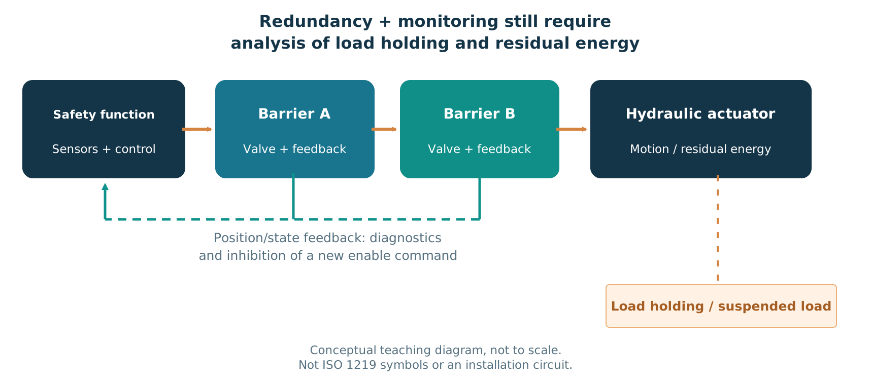
Placing two valves in an arbitrary sequence is insufficient. Their circuit positions, states, operating capabilities, failure behavior and diagnostics must match the specified function. Without this information, it is impossible to claim that a press will never move if one valve fails. The conceptual drawing shows responsibilities; it does not establish this property for an installation.
Common-cause failures matter as well. Fluid contamination, a shared power supply or a common connection may affect both channels. The required independence and measures against common causes must be assessed. Duplicating components does not automatically eliminate a cause capable of affecting both.
This material is educational. It is not a design, assessment report, valve selection or commissioning procedure. A safe installation requires risk assessment, real application data, engineering design and validation by appropriately qualified professionals.
Ministério do Trabalho e Emprego — Manual de Aplicação da NR-12 →
ISO — ISO 13849-1:2023 — Safety-related parts of control systems →
Dynamic monitoring: command, feedback and the actual effect
An electrical output indicates that a command was issued. Feedback may indicate a component’s observed position or state. The hydraulic effect is a separate matter: did flow actually stop? Did the load remain supported? Evaluating the function requires distinguishing these three levels of information.
Dynamic monitoring means evaluating expected behavior throughout relevant transitions, rather than observing only a static “healthy” signal. Spool-position sensors, microswitches or proximity sensors can provide feedback. Depending on the architecture, pressure measurements may add information about hydraulic conditions. The logic compares signals and conditions at defined points and responds to inconsistencies according to the function.
Bosch Rexroth manual RE 18300-31, edition 09.2022, describes position monitoring using a Hall sensor associated with a magnet in the spool. The document emphasizes that the sensor alone is not a safety device. Its presence does not justify assigning a performance level, category or safety certification to the valve-and-manifold assembly.
Consistent position feedback alone does not demonstrate perfect sealing, absence of pressure or absence of movement. Diagnostic coverage depends on the failure modes, device, logic and application. When a fault is detected, the response and inhibition of further actuation must follow the defined safe behavior. Resetting does not repair a physical fault.
Bosch Rexroth — Spool Position Monitoring — RE 18300-31 / 09.2022 →
Stopping flow, holding a load and releasing energy are separate functions
Interrupting supply may control a commanded movement without demonstrating that a mass will remain supported. A suspended tool may require a specific function to prevent dangerous descent. Conversely, limiting overpressure does not mean that the tool is supported. Each function addresses a hazard and must be assessed under the conditions in which it is needed.
A simple check valve, pilot-operated check valve, counterbalance valve and double-block arrangement have different principles and applications. Selection depends on the load, pressures, pilot operation, losses, allowable leakage, failures and required response. A component cannot be selected solely by its commercial name or because it has a sensor.
Retained energy needs its own assessment. Part of a circuit may remain pressurized after a stop; in another scenario, releasing pressure may allow a previously hydraulically supported mass to fall. “Depressurize everything” is therefore not a universal solution either. The sequence and means of energy control must preserve the protective functions.
During maintenance, mechanical load-holding measures and isolation procedures may be necessary depending on the machine and applicable requirements. A logical stop state does not replace physical protection for working beneath a load. Annex VIII of Brazil’s NR-12 addresses hydraulic requirements and mechanical devices separately, with conditions and exceptions that must be examined.
Ministério do Trabalho e Emprego — NR-12 — texto oficial consultado em 11/10/2026 →
Worked example: a hypothetical 100 mm cylinder
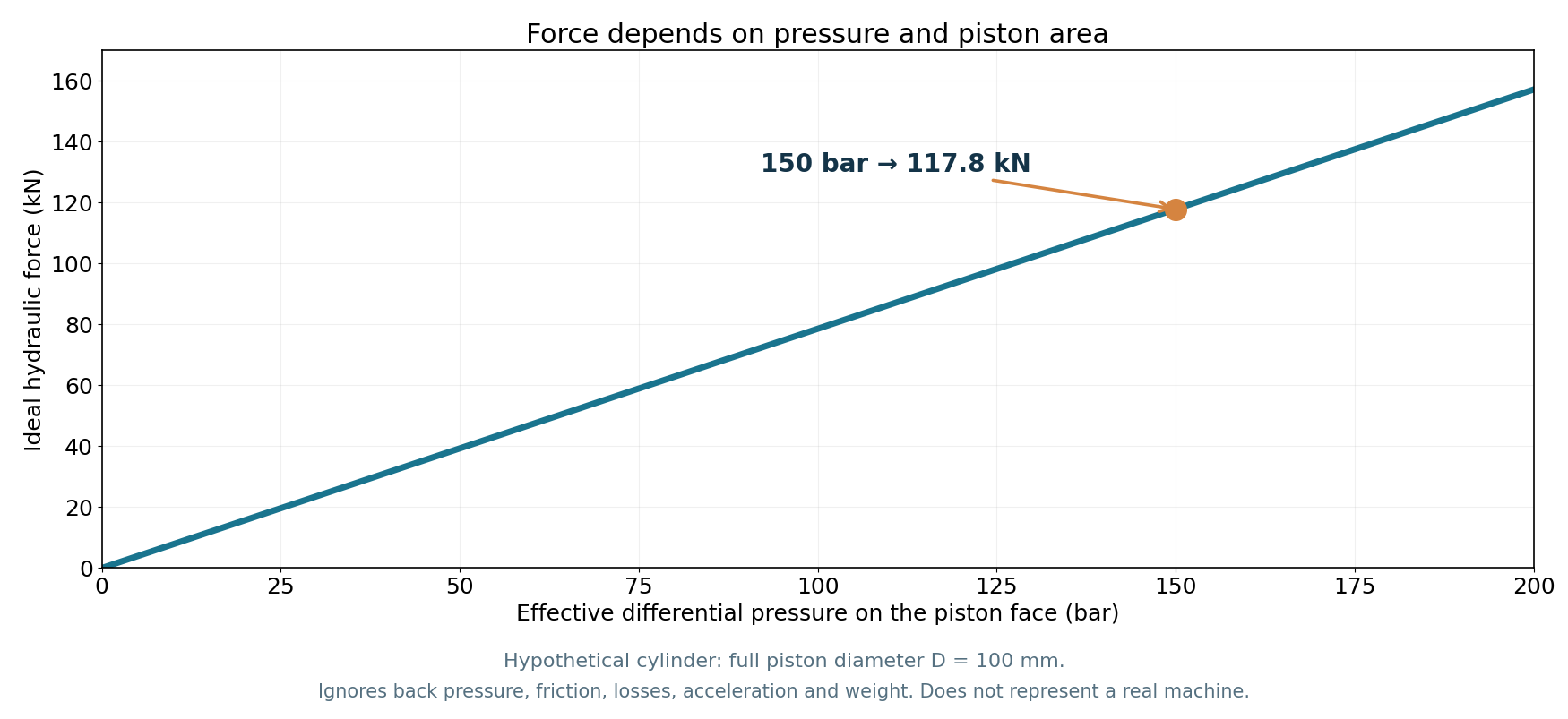
Consider a generic cylinder with an internal diameter D = 100 mm, rod diameter d = 50 mm, an idealized effective pressure differential of 150 bar and an inlet flow of 20 L/min. These values are editorial choices for teaching the relationships, not data from a real machine. To calculate the isolated force in each direction, we assume the stated effective pressure acts on the corresponding face, with no opposing contribution in the model.
Converting the units: D = 0.100 m; d = 0.050 m; Δp = 15,000,000 Pa; Q = 20/1,000/60 = 0.0003333 m³/s. The full-bore area is 0.007854 m², and the annular area is 0.005890 m². Applying an effective 150 bar in each case gives ideal forces of approximately 117.8 kN in extension and 88.4 kN in retraction.
With 20 L/min entering the full-bore chamber, ideal speed is 0.0424 m/s, or 42.4 mm/s. If the same flow enters the annular chamber, ideal retraction speed is 56.6 mm/s. This follows from the difference in areas; it does not mean a real machine will achieve these values under its actual load and control conditions.
The ideal hydraulic power associated with 150 bar and 20 L/min is 5,000 W, or 5.0 kW. This is not the pump’s electrical power consumption, which involves the drive assembly and its efficiencies. The curve in the illustration uses only the 100 mm full-bore face and shows F = Δp × A from 0 to 200 bar.
The example disregards friction, losses, backpressure, weight, acceleration, compressibility and leakage. It does not calculate stopping time or distance, demonstrate load holding after pressure loss, or prove redundancy. Supply pressure, effective pressure on a face and available net force must not be confused.
| Result | Ideal calculation | Approximate value |
|---|---|---|
| Extension area | πD²/4 | 0.007854 m² |
| Retraction area | π(D² − d²)/4 | 0.005890 m² |
| Extension force | 15,000,000 × A_full | 117,810 N = 117.8 kN |
| Retraction force | 15,000,000 × A_ann | 88,357 N = 88.4 kN |
| Extension speed | Q/A_full | 0.0424 m/s = 42.4 mm/s |
| Retraction speed | Q/A_ann | 0.0566 m/s = 56.6 mm/s |
| Hydraulic power | Δp × Q | 5,000 W = 5.0 kW |
Four situations for examining the function
The matrix below organizes engineering questions. It is neither a complete failure analysis nor a certification of tolerance to every possible fault. For each situation, the important point is to demonstrate the function’s response in the defined context and conditions.
A detected fault needs appropriate treatment before recovery. Seeing an expected position signal again does not prove that the fault has disappeared or authorize automatic resumption. The function must specify diagnostics, response, reset conditions and prevention of unexpected restart.
| Observed situation | Relevant risk | What must be demonstrated |
|---|---|---|
| The control requests a stop | Flow or movement continues after the command is removed | Safe behavior of the final elements in the intended scenario |
| A valve does not return | An undetected failure in one channel | Diagnostics, response and inhibition of another cycle |
| Hydraulic supply is interrupted | Movement due to gravity or retained energy | Load holding, protection against falling and residual-energy control |
| A common cause affects both channels | Redundancy compromised by the same source | Common-cause measures, reliable data and validation |
Brazil’s NR-12: specific requirements for presses within its scope
The federal text published by Brazil’s Ministry of Labor and Employment (MTE), consulted on October 11, 2026, sets requirements in Annex VIII, items 2.6 through 2.6.5, for hydraulic presses covered by that annex. It addresses a hydraulic safety valve block or equivalent system, redundant valves interrupting the main flow, dynamic monitoring and manual reset after a detected fault. The annex’s scope and other requirements must also be read.
Item 2.6.3 links monitoring by microswitches or proximity sensors to connection with a safety interface classified as category 4 under ABNT NBR 14153. This does not mean that an individual sensor has that category or that every circuit using it achieves the required performance. The interface and function must meet the requirement and suit the application.
The rule also distinguishes protection against a falling load from interruption of flow. Item 2.6.4 allows one of the redundant valves to perform the load-holding function, provided it actually fulfills that function under the required conditions. Do not conclude that a third valve is always required, or that load holding has been established merely because two valves are present.
In an equivalent system, the load-holding valve must be mounted directly on the cylinder body. Only where this is not possible may it be connected by rigid piping with welded or flanged connections, under the conditions specified by the rule. Where pressure intensification could cause damage, a directly operated pressure-relief valve is required between the cylinder and the load-holding valve, blocked or locked against unauthorized adjustment. Merely calling a circuit “equivalent” is insufficient: its arrangement and response must meet the applicable requirements.
Annex VIII must not be generalized to every hydraulic machine. Item 1.2.1 excludes machines covered by Annex X; item 2.12 sets specific conditions for presses with an ascending table, and item 2.13 addresses the exception to the mechanical load-holding device for presses with horizontal movement. These conditions are not general exemptions from safety requirements and must be examined in full.
Ministério do Trabalho e Emprego — NR-12 — texto oficial consultado em 11/10/2026 →
Ministério do Trabalho e Emprego — Manual de Aplicação da NR-12 →
Technical standards: scope matters as much as the edition
ISO 4413:2010 addresses general rules and safety requirements for hydraulic fluid power systems and their components. ISO 13849-1:2023 addresses safety-related parts of control systems and can involve hydraulic technology. PLr is the required performance level established for the function; the achieved PL must be demonstrated for the implemented architecture.
ISO 16092-3:2017, used together with Part 1 of the series, covers hydraulic presses for cold working metal or material partly made of cold metal, as stated in its official scope. It must not be applied indiscriminately to every press used for a different process or material.
Knowing a standard’s number does not replace checking its scope, edition, applicable requirements and relationship to local rules. Official ISO pages and Brazilian federal documentation provide references for this verification. This article summarizes concepts without reproducing the full text of the standards.
ISO — ISO 4413:2010 — Hydraulic fluid power →
ISO — ISO 13849-1:2023 — Safety-related parts of control systems →
An assessment that follows the path of energy
Begin by describing hazardous movements, loads, pressure sources and stored energy. Assess risks and define the required functions, their safe states and behavior in response to the failures considered. Only then select an architecture and components compatible with those objectives.
The analysis must follow the actual hydraulic path: how flow is controlled, what holds the load, where pressure may remain and which causes can affect more than one channel. Establish monitoring, response and reset conditions. Where applicable, calculate and demonstrate the function’s performance level, considering the subsystems involved.
Finish with review and validation through appropriate analysis and testing, maintenance documentation and change control. This conceptual sequence is not a procedure for energized testing. Replacing a valve, changing logic or altering pressure can change the function and requires the relevant assessment.
Safety must reach the movement
Two valves may form part of a redundant architecture; feedback may contribute to diagnostics; a load-holding valve may control the descent of a mass. Each statement, however, depends on the function, components and demonstrated conditions. Counting parts or observing the absence of an electrical signal does not complete the analysis.
A safety function does not end at the electrical signal. It fulfills its objective only when the hydraulic system also controls movement, recognizes faults and accounts for energy that remains stored.
Frequently asked questions
What is a hydraulic safety valve block?
It is an assembly of hydraulic functions organized to participate in controlling a machine’s risks. Depending on the architecture, it may combine blocking or directional valves, redundant paths and monitoring devices. Its name or assembly in a single manifold does not, by itself, demonstrate safety performance. Check the functions to be performed, failure behavior, required load holding, control elements and validation of the application.
Why use redundant hydraulic valves?
Redundancy supports an architecture in which the failure considered in one channel does not defeat the required function under the design conditions. It must exist in the effective hydraulic paths and be accompanied by analysis of diagnostics, response and common causes. Two valves without suitable integration do not prove this property. Contamination, shared supplies and common connections can compromise both channels and must be included in the function’s assessment.
What does dynamic valve monitoring mean?
It means checking the expected behavior of components during relevant transitions, using suitable feedback and logic that identifies inconsistencies. A signal may indicate position or state; it does not automatically demonstrate the absence of leakage, pressure or movement. The design must define what is observed, when to evaluate it, how to respond and which conditions permit recovery. Useful diagnostics depend on the failure modes considered and the actual capabilities of the devices and architecture.
Is a monitored valve automatically safety-certified?
No. A position sensor adds information, but its presence does not assign a performance level or category to the assembly. Bosch Rexroth manual RE 18300-31 emphasizes that the sensor alone is not a safety device. The function must be examined together with its channels, logic, outputs, final elements and operating conditions. Certifications and declared capabilities require verification in the corresponding documentation; they cannot automatically be transferred from one component to the whole machine.
How do directional, check and pressure-relief valves differ?
A directional valve selects flow paths. A check valve allows or prevents flow according to its operating principle and may help hold a load in a suitable application. A pressure-relief valve limits overpressure through its intended path. These are different functions, even when a circuit combines components to perform them. Pilot-operated versions, counterbalance valves and double-block arrangements are not automatic substitutes. Selection depends on the loads, pressures, failures and responses required by the design.
Does switching off the pump automatically prevent cylinder movement?
No. Pressure may remain in isolated volumes or accumulators, and gravity may still move a load. Switching off the pump does not demonstrate that a tool remains supported or that residual energy is absent. Valve states, flow paths, leakage and applicable protective measures must also be assessed. Stopping, load support and intervention conditions need to be demonstrated as separate functions and measures, according to the risk and the machine.
How is hydraulic cylinder force calculated?
For an ideal model with one effective face, use F = Δp × A, with pressure in Pa, area in m² and force in N. The full-bore area is πD²/4; the annular area excludes the rod. In double action, the net hydraulic contribution considers pressure on both areas: p_full A_full − p_ann A_ann. Friction, weight and acceleration further affect available force. This result does not calculate stopping behavior, load holding or functional safety.
What does NR-12 require for hydraulic presses?
For presses within its scope, Brazil’s NR-12 Annex VIII sets requirements for a hydraulic safety valve block or equivalent system, redundancy, dynamic monitoring, fault response, reset and protection against falling loads. Interfaces, equivalent systems and other measures have specific conditions. Read the scope and exceptions: the rule must not be applied indiscriminately to every hydraulic machine. Compliance requires assessing the actual installation and other relevant requirements, rather than simply buying two valves.
References
- NR-12 — texto oficial consultado em 11/10/2026Ministério do Trabalho e Emprego
- Manual de Aplicação da NR-12Ministério do Trabalho e Emprego
- ISO 4413:2010 — Hydraulic fluid powerISO
- Spool Position Monitoring — RE 18300-31 / 09.2022Bosch Rexroth
- Directional seat valves — M-SED6Bosch Rexroth
- ISO 13849-1:2023 — Safety-related parts of control systemsISO
- ISO 16092-3:2017 — Hydraulic pressesISO
- Fluid Lexicon — Safety valveHAWE Hydraulik