
Understand how a safety PLC works, from the sensor to the safe output. Explore two-hand control, faults, EDM and an educational simulator.
Two buttons pressed: is that enough?
Imagine a hypothetical industrial press. The operator presses one button with each hand to request a movement. The rule seems simple: if A and B are pressed, the machine may operate. But what if a button is stuck? What if the signals arrive too far apart? What if the contactor did not open after the previous cycle? Engineering must answer these questions before turning two signals into an authorization.
In this component study within our Engineering series, we will follow a safety function from its input to the element that acts on movement. The Schmersal PSC1-C-100 provides a concrete controller reference; the drawings and two-hand station are generic illustrations. The laboratory below is an independent simulation with no connection to a machine, controller or industrial network.
Standard PLCs and safety PLCs: different responsibilities
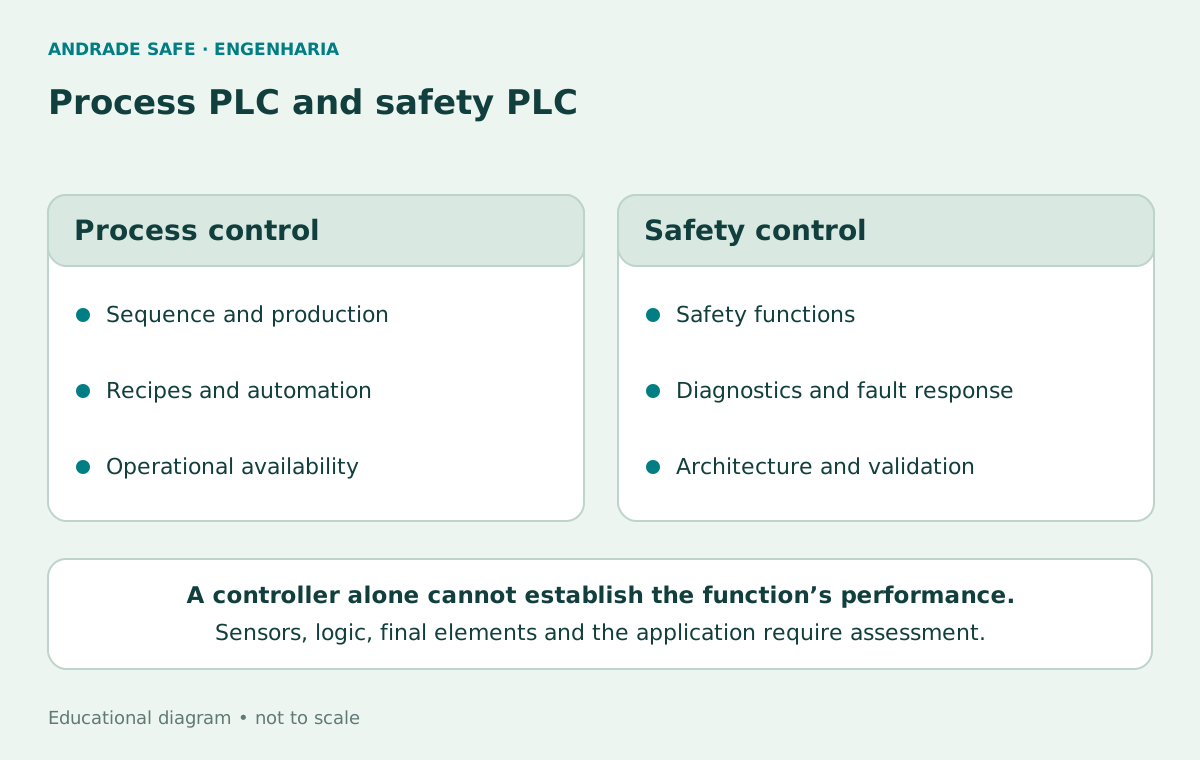
A process PLC organizes production: sequences, recipes, temperature, counting and communication with the operator interface. A safety controller handles functions whose response to faults must be specified and demonstrated. It is more than a standard PLC with a password or an input named “emergency”.
Controllers intended for safety use architectures, diagnostics and development processes suited to the purpose declared by the manufacturer. Redundancy and internal checks can help detect faults and bring outputs to the intended state. Product capability depends on its manual, configuration, components and application conditions; a “safe” label does not replace an assessment of the complete function.
The two types can coexist. The process PLC may receive status information to display an alarm or organize a sequence. However, this conventional information does not automatically become a safety channel. Prevention of hazardous movement must remain supported by the safety-related architecture, including when supervisory communication fails.
| Aspect | Process PLC | Safety controller |
|---|---|---|
| Main purpose | Organize production and operation | Execute safety-related functions |
| Faults | Handled according to the automation design | Diagnostics and behavior defined for the function |
| Supervisory signals | Indicators and status communication | Do not replace the safety chain |
| Demonstrable result | Automation performance | Contribution to a validated function; not machine certification |
A real product: PSC1-C-100
The official catalog for the PSC1-C-100, item 103056776, identifies a modular controller supplied at 24 V DC. The reference consulted has 14 safe inputs, 20 configurable safe I/O, four safe semiconductor outputs and two safety relay output contacts. The catalog also lists six signaling outputs and six test pulses. I/O means input or output; a configurable point must not be counted in both roles at once.
These figures describe the reference consulted, not every product with “PSC1” in its name. Modules, variants, parameters and electrical limits must be checked in the corresponding documentation. A semiconductor output and a relay contact do not necessarily share the same behavior, load capacity, diagnostics or compatibility with the connected device.
SafePLC2 is the environment specified by Schmersal for developing the family’s logic. Function blocks help express safety behavior, but selecting a software block does not prove that sensors, wiring, final elements and installation meet the requirement. The program, its parameters and the application need review and validation under the applicable procedures.
The documentation declares the possibility of applications up to PL e, category 4 and SIL 3 under the specified conditions. This is a declared equipment capability; it does not mean “guaranteed PL e” for a press or for any function connected to it. The level achieved by the chain depends on all its subsystems and their integration.
The references consulted were the PSC1-C-100 V3.0 installation manual, version 37E, February 2026, valid from the firmware specified on its cover, and the SafePLC2 V2.9 manual, corresponding to software version 1.7.1.78xx. These are reading references; compatibility with the equipment and software actually used must be confirmed before application.
Schmersal — PSC1-C-100 — 103056776 →
Schmersal Brasil — CLP de Segurança Modular Programável PSC1 →
Schmersal — PSC1-C-100 Installation Manual — V3.0 / 37E / 02-2026 →
Schmersal — SafePLC2 Programming Manual — V2.9 / 1.7.1.78xx →
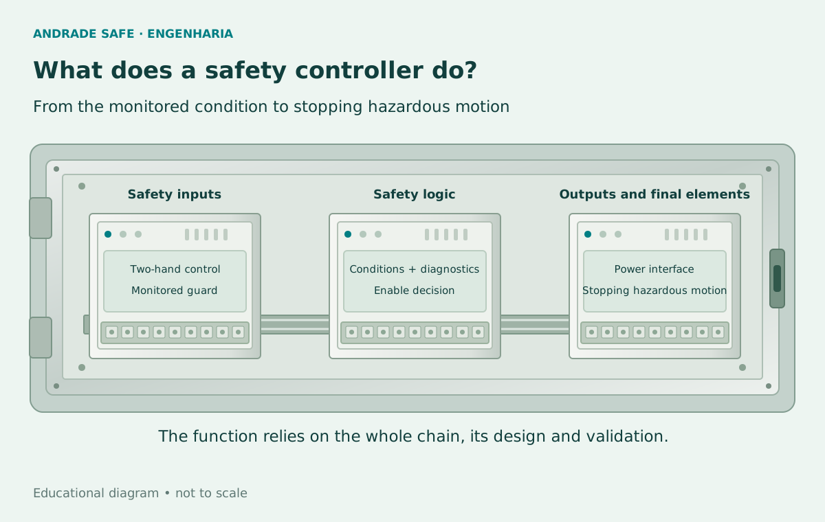
The chain: detect, decide and act
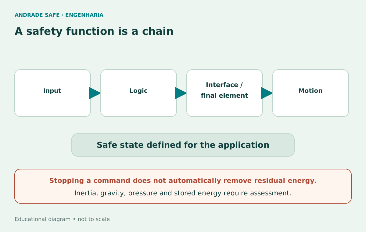
At the input, devices provide signals about commands and conditions. The logic evaluates those signals. Outputs command interfaces and final elements. Ultimately, those elements must bring the machine to the safe state defined for the hazard. The path does not end at a green light on the panel.
In a generic example, buttons feed the two-hand evaluation, the logic withdraws or grants an authorization, and suitable devices act on energy or movement. De-energizing an output may form part of the response, but “no voltage” is not a universal synonym for “no risk”: inertia, gravity, stored pressure and residual energy must be considered.
When an intermediate interface exists, its role must be clear. A relay, contactor, drive or valve may belong to the chain that needs assessment. Replacing only the controller while retaining an unsuitable final element does not correct the entire function. The design must define what will be detected, what should happen and how to confirm it happened.
Two-hand control: timing, continuity and intent
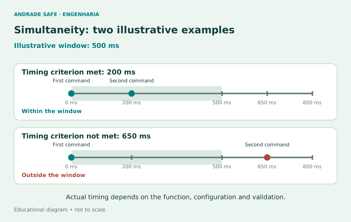
In the laboratory example, A and B must be actuated no more than 500 ms apart and remain actuated to maintain the logical permissive. A 200 ms delay passes this comparison; 650 ms does not. A millisecond is one thousandth of a second: 500 ms equals 0.5 s. The times are educational values selected to illustrate a configuration; they do not, by themselves, establish compliance of a real device.
Simultaneity is a timing condition, not simply the observation that both signals are high. The system must distinguish two new actuations from a signal already held. Therefore, in the model, both buttons must be released before another attempt. Anti-repeat prevents releasing and pressing only one button while the other remains held from producing another permissive.
Releasing either button withdraws the permissive in the model. In a machine, withdrawing authorization and reaching the safe state are separate events: processing, actuation and stopping times are involved, as is the position of the control devices. The result must be evaluated for the intended function and control type. Two-hand control does not automatically protect other people or the entire machine area.
Physical installation also matters. Position, separation, prevention of unintended actuation or defeat, access by other people and the relationship to the hazard require analysis. ISO 13851 addresses two-hand control devices; the application must consider the relevant requirements and other protective measures. The simulator does not determine installation distance or the device’s normative category.
In Brazil, item 12.4.3 of NR-12 requires the two-hand control devices within its scope to operate synchronously with a difference of no more than 0.5 s, along with other monitoring, continuity and restart conditions. The 500 ms chosen for this example matches that time limit, but satisfying the window alone does not satisfy the full set of requirements for the function.
Ministério do Trabalho e Emprego — NR-12 — arquivo oficial atualizado 2025 →
Test pulses: what can they reveal?
Two input channels do not, by themselves, guarantee independence. A fault can affect both or make a signal appear valid. Depending on the architecture and the configuration permitted by the manufacturer, test pulses and monitored signals help detect certain faults, such as some short circuits between channels or to the supply.
The idea is to compare an observed signal with expected behavior instead of interpreting only a continuous level. However, diagnostic coverage depends on the input type, the connected device, conductor routing and possible faults. It is incorrect to promise that the same pulses will detect every short circuit, stuck contact or defect.
Electrical and timing compatibility must be checked. Electronic sensor outputs, contacts and interfaces may require different configurations. The drawings in this article show concepts only; they do not provide terminals, pin assignments, jumpers or installation wiring. The laboratory likewise produces no real pulses and calculates no diagnostic coverage.
Schmersal — PSC1-C-100 Installation Manual — V3.0 / 37E / 02-2026 →
EDM: the output commanded, but did the final element respond?
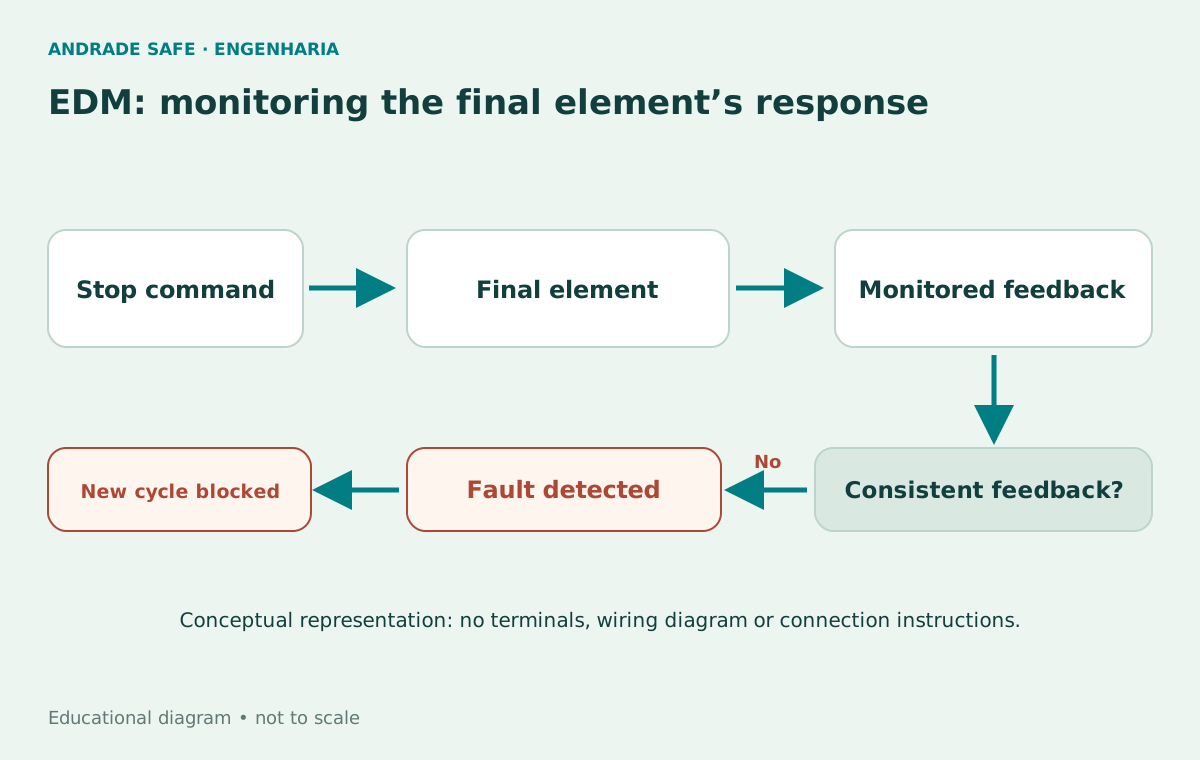
EDM means external device monitoring. The logic observes feedback associated with the state of final elements. If that feedback does not match the expected state at the specified time, a new enable may be blocked. This prevents the design from asking only whether the controller sent a command.
Consider a contactor that should open after the output is withdrawn. If a main contact remains closed, suitable feedback may indicate that the rest state was not reached. Where applicable and correctly selected, contactor mirror contacts or mechanically linked relay contacts establish useful relationships between states. An arbitrary auxiliary contact must not automatically be treated as sufficient proof.
EDM is neither a universal movement sensor nor proof of an absence of energy. Healthy feedback may convey something about the monitored device without demonstrating that pressure has dissipated, a shaft has stopped or the entire function is intact. The devices, expected states, checking times and fault response must be defined in the architecture.
In the laboratory, “EDM fault” is a logical switch representing incompatible feedback. It does not reproduce contact dynamics, response times, welding, the SafePLC2 library or fault analysis. Restoring feedback does not grant a start: it only allows the illustrated recovery and reset sequence to proceed.
Schmersal — PSC1-C-100 Installation Manual — V3.0 / 37E / 02-2026 →
Schmersal — SafePLC2 Programming Manual — V2.9 / 1.7.1.78xx →
Reset is not start
After an emergency or feedback fault in the model, the simulated condition must be removed, the buttons released and a reset performed. Reset restores the possibility of accepting a new request. The reset command alone never grants the movement permissive in this laboratory.
Releasing an emergency stop device also does not mean restarting is appropriate. A real design must prevent unexpected start-up and consider people’s situation, visibility, control location and remaining hazards. ISO 14118 addresses prevention of unexpected start-up; procedures, energy isolation and design measures have distinct roles.
To make this distinction visible, the simulation includes a separate “Request cycle” button. This sequence is a pedagogical choice for the laboratory, not a universal requirement for every real two-hand control to have an additional button. Start intent and restart logic must be specified for each application.
PLr and PL: define the requirement, then demonstrate performance
PLr is the required performance level for a safety function, established through risk assessment and applicable criteria. PL is the performance level achieved by the implemented function. They are not interchangeable values or properties determined solely by the controller model.
ISO 13849-1:2023 addresses safety-related parts of control systems. Assessment involves architecture, component reliability, diagnostic coverage, common cause failures and other relevant requirements. Sensors, logic, interfaces and final elements must be considered within the function; use conditions and fault exclusions require justification.
Equipment capable of being used in applications up to PL e may be part of a chain that fails to achieve the required PLr. Nor does adding commercial labels produce a higher level. Demonstration depends on design and validation using appropriate analysis and testing. ISO 13849-2 is a reference for validation within this standards family.
NR-12 sets Brazilian requirements for machinery and equipment safety. Selection of measures must start with hazards and the conditions of operation, maintenance and intervention. Safety automation is part of this work; it does not replace physical guarding, residual energy management, documentation, training or measures required for the specific application.
Ministério do Trabalho e Emprego — NR-12 — arquivo oficial atualizado 2025 →
Ministério do Trabalho e Emprego — Manual de aplicação da NR-12 →
Try seven situations in the laboratory
Start with the 200 ms scenario. Observe that both buttons, the request, the emergency condition and feedback participate in the decision. Then compare the 650 ms delay and actuation of only one button. In the anti-repeat test, A remains pressed while B is released and pressed again: the permissive remains blocked.
Automatic scenarios use virtual times and run immediately. In the manual controls, the interval is measured between your clicks. Clicking to press or release is an interface convention with no physical equivalence to holding two hands on actuators. This difference is essential to avoid interpreting the experiment as a test of a two-hand station.
Test the emergency condition and EDM fault during a permissive. Then examine “New cycle without reset”: the scenario clears the emergency condition and releases both buttons, but the request remains blocked because reset is still pending. The history records the sequence. “Restart experiment” clears the simulation; it does not represent an unlocking feature on a machine.
Two-hand control laboratory
Educational simulation. Not safety software or an implementation specification.
Manual controls: click to press or release. Scenarios run an immediate virtual sequence with no industrial connection.
Seven automatic scenarios
- Button A
- RELEASED
- Button B
- RELEASED
- Cycle request
- NO
- Rearm pending
- NO
- Emergency stop
- NORMAL
- EDM feedback
- HEALTHY
Experiment restarted: output disabled; waiting for a request.
History — newest first
- Experiment restarted: output disabled; waiting for a request.
State model without physical test pulses, stopping time, PL calculations or real energy. The separate request is a teaching choice, not a universal two-hand-control rule. Release both before another attempt; simulated faults require restoration and rearming.
What this experiment teaches — and what it does not calculate
The model teaches relationships between logical states: healthy conditions are necessary, release withdraws the permissive, and simulated faults require recovery before a new request. It does not implement certified software, PSC1 firmware, physical test pulses, internal diagnostics, fault tolerance or deterministic real-time operation.
It does not calculate PL, PLr, SIL, diagnostic coverage, safety distance or stopping time. It does not size contactors, valves, hydraulic circuits or electrical protection. “Permissive granted” means only that the conditions of the educational model were satisfied; it does not prove that any real movement would be safe.
A real engineering application requires specifying functions, consulting compatible documentation, checking sensors and final elements, analyzing faults and energies, testing and validating integration. Laboratory results are not production parameters, commissioning instructions or substitutes for this engineering.
Take the laboratory with you for study
The HTML simulator can be downloaded and opened locally in a browser with JavaScript. It does not connect to industrial systems. The embedded version was adapted to the blog with text in three languages and seven scenarios; the downloadable file is in Portuguese and retains its educational purpose.
The diagrams are original and generic. No installation documentation, customer data or implementation-ready engineering design is available on this page. Use the official references to learn about the equipment and regulatory context, always distinguishing a teaching example from a real specification.
In safety, fault behavior is part of the function
The initial question cannot be resolved by looking at two buttons alone. Signal validity, timing sequence, previous release, feedback from final elements and recovery conditions must all be followed. Each stage has a responsibility and a limit.
Knowing a controller such as the PSC1 helps make these ideas concrete. However, the focus of the design remains the machine’s safety function, with a defined requirement and demonstrated behavior. In machinery safety, a working button is not enough: the architecture must remain safe when something fails.
Frequently asked questions
Can a standard PLC replace a safety PLC?
A conventional PLC does not automatically replace the controller intended for a safety function. The architecture must meet the established requirement and demonstrate its behavior, including sensors, logic and final elements.
What PSC1-C-100 configuration is cited?
The reference consulted, 103056776, has 14 safe inputs, 20 configurable safe I/O, four safe semiconductor outputs and two safety relay output contacts, supplied at 24 V DC. Variants, expansions and limits must be checked in the corresponding manual.
Does the PSC1 guarantee PL e for the machine?
No. The controller’s declared capability does not certify the level of the complete function. The achieved PL depends on the chain’s architecture and components, application conditions and validation against PLr.
Why does the example use 500 ms?
It illustrates simultaneity and matches the maximum 0.5 s difference required by Brazilian NR-12 item 12.4.3 for the two-hand control devices within its scope: 200 ms passes and 650 ms fails. A real application must assess the complete normative requirements, device type and configuration; the simulator does not establish compliance.
What happens when a button is released?
In the model, the permissive is withdrawn and both buttons must be released before another attempt. In a real machine, withdrawing the command and achieving the safe state also depend on final elements, energies and stopping time.
What does anti-repeat prevent?
It prevents obtaining another permissive by releasing and pressing only one button while the other remains held. In the example, a new cycle requires both buttons to be released and a new request.
Does EDM prove that the entire machine is safe?
No. Monitoring observes the specified feedback from external devices. That information does not replace verification of movement, residual energy or the integrity of the entire function.
Are reset and start the same thing?
No. In the laboratory, reset only enables acceptance of a new request; it does not grant the permissive. Clearing a fault or releasing the emergency stop also does not automatically start a cycle.
Can the laboratory be connected to a controller?
No. It is an independent educational simulation with no industrial communication. It is not safety software, an implementation-ready specification, a commissioning tool or machine validation.
Does two-hand control protect everyone?
Not automatically. The function, access to the hazard, other people, positioning, stopping time and other protective measures must be evaluated for the application.
References
- PSC1-C-100 — 103056776Schmersal
- CLP de Segurança Modular Programável PSC1Schmersal Brasil
- PSC1-C-100 Installation Manual — V3.0 / 37E / 02-2026Schmersal
- SafePLC2 Programming Manual — V2.9 / 1.7.1.78xxSchmersal
- NR-12 — arquivo oficial atualizado 2025Ministério do Trabalho e Emprego
- Manual de aplicação da NR-12Ministério do Trabalho e Emprego
- ISO 13849-1:2023ISO
- ISO 13851:2019ISO
- ISO 14118:2017ISO
- ISO 13849-2:2012ISO