
Explore what the TSMC construction accident teaches about temporary steel stability, bolted joints, fall-arrest anchors and common-cause failures.
Steel erection, load paths and fall protection
Original dossier: October 22, 2026; sources rechecked October 23, the publication date. The event occurred October 20 and statements were reported October 21. No official technical conclusion closing the causes was located in the sources checked. Stoppages below are measures reported on October 21, not confirmation that the full scope remained suspended on October 23.
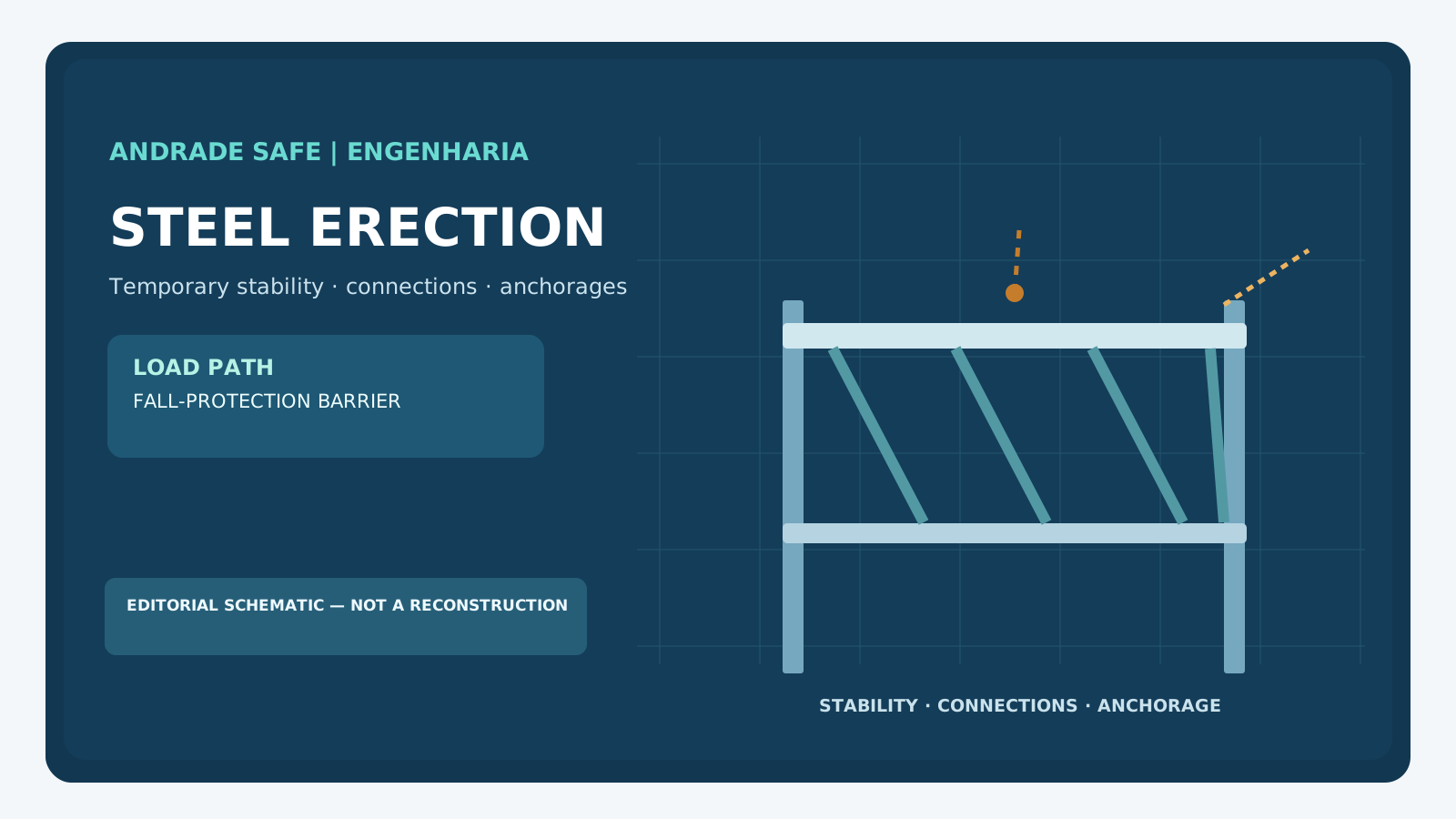
A steel building does not instantly become the final stable structure shown on its drawings. During erection, members pass through temporary configurations: a crane may carry part of the load, connections may be incomplete, columns may rely on temporary bracing, and the structural load path may change with every operation. A fatal accident at the Fab 22 Phase 4 construction project for Taiwan Semiconductor Manufacturing Co. (TSMC), in Kaohsiung, illustrates why engineers must consider the relationship between temporary structural stability and personal fall protection.
On October 20, 2026, four contractor employees engaged in hoisting and installing steel members fell together with structural components while working around the third floor. All four died. On October 21, Taiwan's Central News Agency reported the Southern Taiwan Science Park Bureau's preliminary information: bolts at an external steel connection plate may have fractured, and the workers were reportedly attached to safety ropes whose attachment arrangement might have been affected as the structural component fell. The precise cause and configuration have not been conclusively established. [F1][F2]
The Bureau suspended the relevant Phase 4 steel-hoisting activity pending review of an improvement plan. TSMC also reported voluntarily suspending steel erection at its new-factory construction sites in Taiwan while assisting the investigation. This is the verified status at the reporting cut-off, not a final root-cause determination. [F2]
A clear distinction: established facts, preliminary accounts and open questions
Media reports discussing bolt deterioration or insufficient bolt numbers are important leads for investigators, not proof. A conclusion would require site records, preserved physical evidence, connection geometry, construction sequence, mechanical tests if appropriate, and examination of the entire fall-protection load path.
| Classification | What is known | What cannot yet be inferred |
|---|---|---|
| Confirmed in official statements as reported by CNA | October 20 incident at Fab 22/P4, four fatalities | The technical root cause |
| Preliminary account | A connection-plate bolt problem may have been involved | Fatigue, improper quantity, poor workmanship or design error as a proven cause |
| Preliminary account | Workers had safety ropes; the support for those ropes may have shared the falling assembly | Detailed fall-protection system design, actual anchorage capacities and compliance |
| Response | Hoisting work suspended; wider voluntary TSMC stoppage reported | That inspections, corrective actions or findings have already been completed |
A completed frame is not the same as a frame being assembled
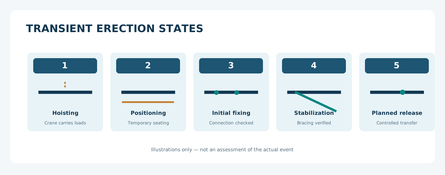
In the final design configuration, loads may be transmitted through established diaphragm systems, completed bracing bays, fixed connections and stable foundations. During erection, some of those restraints may not yet exist. A member lifted into position can be susceptible to rotation, lateral instability and unexpected movements. Temporary connections and bracing may experience forces different from their final-service actions.
A useful erection plan therefore identifies the state of the structure at each hold point: lifting and positioning; temporary seating; initial connection; confirmation of lateral restraints; controlled transfer of load from lifting equipment; and completion of permanent connections. The details must be developed for the actual project by competent designers and contractors. No universal sequence or bolt count should be inferred from this article.
A bolt is not the same as a verified joint
Bolted connections must resist the combination of actions produced by the actual structural geometry. Fasteners may be subjected to shear and tension, while plates can experience bearing, net-section fracture, block shear or local deformation. Eccentricity can introduce moments and uneven force distributions. Contact conditions, bolt pretension where specified, slip, hole geometry, member flexibility and assembly quality all affect performance.
Consider a hypothetical 10 kN force acting with an eccentricity of 0.20 m. Its external moment is M = F × e = 2.0 kN·m. This is a statement of equilibrium, not a direct bolt-force calculation. Dividing the force equally by the number of visible bolts is generally not an adequate design model for an eccentric connection.
For an investigation, relevant questions include: Which bolts and plates were specified for the erection stage? Were temporary fixings reused or altered? Which loads existed before release of the lifting line? Had bracing been completed? What inspections authorized personnel access? No public information cited here answers these questions for the Kaohsiung event.
Worked example: where does the load go?
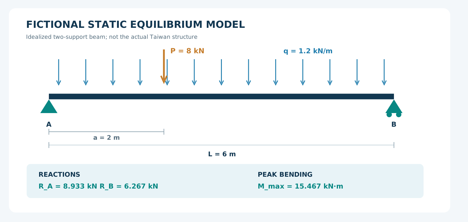
Imagine a fictional simply supported beam 6 m long, carrying a uniformly distributed load of 1.2 kN/m and an 8 kN point load applied 2 m from support A. The following calculation is purely educational and has no relationship to actual TSMC dimensions, masses or loads.
The distributed-load resultant is 7.2 kN, acting 3 m from A. By vertical equilibrium, R_A + R_B = 15.2 kN. Taking moments about A gives R_B × 6 = 7.2 × 3 + 8 × 2, hence R_B = 6.267 kN and R_A = 8.933 kN. At the point-load location, M(2) = R_A × 2 − q × 2²/2 = 15.467 kN·m. In this specific model the shear force changes sign across the point load, making it the positive peak bending moment.
The calculation relies on two supports with the specified constraints. If one support becomes unavailable, the simply supported equations are no longer applicable. Whether the remaining arrangement is stable requires a different structural model incorporating real restraints, connections, bracing and loads. It would be wrong to extrapolate these reactions into a collapse sequence.
Our interactive educational laboratory lets readers vary the span, distributed load, point load and load position. It plots shear force and bending moment. If the user disables a support, it deliberately stops producing simply supported reactions rather than implying a valid alternative design. It does not size steel sections, bolts or safety anchors.
Laboratory: follow the load path
Change span, loads and point-load position to explore static equilibrium, shear V(x) and bending moment M(x). The model uses only its two defined supports. Disabling B makes those results unavailable; it does not automatically create a cantilever or predict collapse.
For 0 ≤ x ≤ L: RB = (qL²/2 + Pa)/L; RA = qL + P − RB; V(x) = RA − qx − P·H(x−a), with a point-load jump; M(x) = RAx − qx²/2 − P·max(0,x−a). L and x use m, q uses kN/m, P and reactions use kN, and M uses kN·m. H represents passing from one side of the concentrated load to the other; the diagram shows one-sided values.
There are no strength, buckling, deflection, connection, global-stability, falling-person or anchorage-capacity checks. Peak moment comes from analytical candidates for the model rather than just the highest sampled graph point.
Laboratory: load paths
Fictitious simply supported beam. Change loads and geometry to explore equilibrium and internal actions; these values do not represent the Taiwan project.
The model does not verify resistance, stability, deformation, dynamics, bolts, anchors or fall protection and cannot authorize work.
Fictional parameters
Static equilibrium
- Reaction A
- 8.933 kN
- Reaction B
- 6.267 kN
- Peak |M|
- 15.467 kN·m
- Peak position
- 2 m
RB = (qL²/2 + Pa)/L · RA = qL + P − RB
M(x) = RA·x − q·x²/2 − P·max(0, x−a)
Shear force and bending moment
V jumps at the point load; values on its two sides differ. The diagrams show internal actions between the supports.
| x (m) | V on left (kN) | V on right (kN) | M (kN·m) |
|---|---|---|---|
| 0 | 8.933 | 8.933 | 0 |
| 1.5 | 7.133 | 7.133 | 12.05 |
| 2 | 6.533 | -1.467 | 15.467 |
| 3 | -2.667 | -2.667 | 13.4 |
| 4.5 | -4.467 | -4.467 | 8.05 |
| 6 | -6.267 | -6.267 | 0 |
CSV uses explicit units and decimal points. It records inputs, reactions and values on both sides of the point load.
The hidden dependency in fall-arrest systems
A full-body harness is only one part of personal fall protection. A working system includes the anchorage structure, anchorage and device, connectors, lanyard or self-retracting device, energy management, fall clearance, trajectory, compatibility and rescue arrangements. Being clipped to a safety line does not establish that the entire load path will remain available under all foreseeable structural changes.
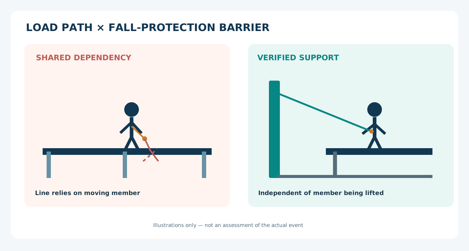
Picture an illustrative scenario where a worker stands on a member being erected and clips their line to an attachment that relies on the same temporarily unstable member. Losing that member could remove both the working surface and the fall-protection reference. Now consider a system independently engineered and verified on a stable structure that is not dependent on the member under erection. This configuration addresses that particular shared dependency, but it is not automatically safe: strength, dynamic forces, sharp edges, fall clearance, rescue and interactions with adjacent works still require engineering verification.
Two separate anchor rings do not constitute genuine independence if both depend on the same vulnerable component. Conversely, separation from a work platform is not sufficient if the surrounding support structure may fail in the same event. This is the principle of a common-cause failure: a single event can undermine apparently distinct controls.
How Brazilian and US requirements illuminate the engineering question
Taiwanese construction sites are governed by Taiwanese requirements. The Brazilian and US documents below are comparative technical references; neither should be presented as a legal finding about this incident.
In Brazil, NR-18, section 18.7.5.1 places the erection, maintenance and dismantling of steel structures under a legally qualified professional. Section 18.7.5.2 requires the personal fall protection system (SPIQ) and means of access to be covered by the site's PGR. Brazil's NR-35 Annex II, section 3.1.1 requires the structure forming part of an anchorage system to withstand the maximum applicable force; section 3.2 addresses the responsible qualified designer and applicable standards for structural anchors and fixings. [N1][N2]
As an explicitly US-specific example, OSHA 29 CFR 1926.756(a)(1) regulates the release of the hoisting line in specified solid-web steel-member connections, with stated fastening requirements and exceptions. It is not a universal design rule or a Brazilian bolt-count requirement. OSHA 1926.502(d)(15) addresses independent attachment relative to anchorages supporting or suspending platforms, with prescribed alternatives for anchor capacity or qualified design. The exact scopes of these US provisions must be respected. [N3][N4]
When checked on October 23, 2026, the official NR-35 PDF already included a July 2026 amendment despite retaining “2025” in its filename. Annex II section 3.2 requires structural anchors and fixings to be designed and built under a legally qualified professional’s responsibility, meeting national technical standards or applicable international standards where national ones are absent. [N2]
Seven questions before steel-erection work proceeds
These are engineering prompts, not a complete regulatory checklist or a substitute for a project-specific erection plan. The relevant assessment must also address emergency rescue and the hierarchy of collective and individual controls.
- Has the temporary structure been analysed at every planned erection stage, including the effect of wind, lifting and changing load paths?
- Are temporary restraints and their removal conditions shown in the method statement?
- Have initial connections been installed, inspected and released according to the engineering plan?
- Are workers kept clear of suspended loads, and are safe access and exclusion zones coordinated with lifting activities?
- Does the fall-protection anchorage rely on any component that may move, rotate or detach during the task?
- Who controls handovers between crane operations, steel erection, bolting, welding and inspections, including subcontractors?
- Is there a stop-work process when actual site conditions diverge from the approved sequence?
What a competent investigation must establish
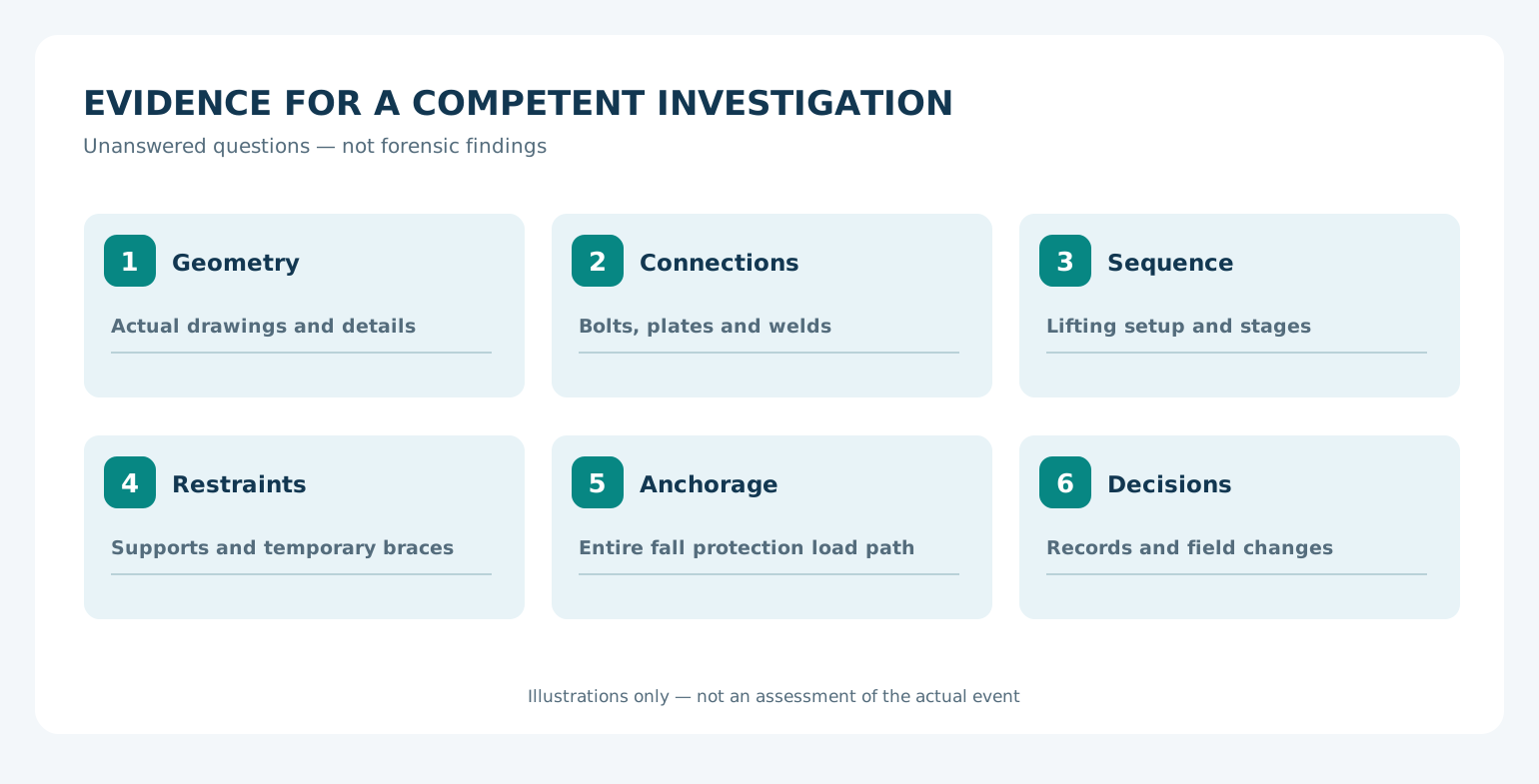
The evidence trail may include drawings and erection procedures; inspection records; lifting plans and logs; photographs taken before the event; fastener traceability; fracture surfaces; plate deformation; field changes; temporary bracing; anchor design; and fall-protection configuration. Fractography, dimensional inspection or structural analysis might be appropriate, depending on what physical evidence remains. None can be replaced by visual speculation about media photographs. [F1][F3]
Connect fundamentals and investigation
Metal fatigue provides fundamentals for possible mechanisms without diagnosing the bolts in this event. Tribology and bearings reinforces the distinction between appearance, hypotheses and confirmed causes. Accident investigation beyond blame, in Portuguese, discusses evidence preservation and learning. These are complementary references for erection planning.
Engineering takeaway
During steel erection, safety is not a checklist of independently purchased items. It is the integrity of load paths and protective barriers throughout transitions between temporary states. An apparently adequate harness cannot compensate for an anchorage whose supporting structure has not been verified. The question worth asking on every site is: If this member loses stability at this stage, which other protective measures depend on it?
Andrade Safe Engenharia — Safety as strategy, not bureaucracy.
Laboratory and study materials
All five figures are educational editorial diagrams, not geometrically faithful reconstructions of the Taiwan site. The kit preserves supplied articles, illustrations and laboratory alongside revised materials. Fictional calculations and engineering questions do not replace design, site assessment or work authorization.
Open standalone laboratory — PT/EN/ES →
Download reference results CSV →
Download kit with articles, diagrams and laboratory →
Sources and checked references
[F1] CNA — preliminary authority account, 21/10/2026 →
[F2] Focus Taiwan / CNA — deaths and work suspension, 21/10/2026 →
[F3] CNA — investigation, 21/10/2026 →
[N1] MTE — NR-18 (official consolidated text) →
[N2] MTE — NR-35, Annex II (official consolidated text) →
[N3] OSHA — 29 CFR 1926.756, Beams and columns →
Frequently asked questions
Does a harness guarantee fall prevention?
No. The entire engineered system and its support must function under relevant conditions.
Were bolts confirmed as the root cause in Taiwan?
No; bolt-related explanations remained preliminary at the October 22 reporting cut-off. [F1]
Is a separate anchor automatically safe?
No. Its full structural load path, expected forces and compatibility must be assessed.
Does this simulator calculate fall-arrest anchors?
No. It only visualizes static equilibrium for a simple beam with two supports.
What happens when a support is removed in the laboratory?
The simply supported calculation stops. Another behavior would require a new model with the real restraints; the result determines neither stability nor collapse.
References
- CNA — preliminary authority account, 21/10/2026CNA / Focus Taiwan
- Focus Taiwan / CNA — deaths and work suspension, 21/10/2026CNA / Focus Taiwan
- CNA — investigation, 21/10/2026CNA / Focus Taiwan
- MTE — NR-18 (official consolidated text)MTE
- MTE — NR-35, Annex II (official consolidated text)MTE
- OSHA — 29 CFR 1926.756, Beams and columnsOSHA
- OSHA — 29 CFR 1926.502, Fall protectionOSHA
- OSHA — Steel Erection, Structural StabilityOSHA