
Learn why bearings fail before their rated life: friction, wear, lubrication, contamination, mounting, contact fatigue and L10 life.
The catalogue and the actual application
Bearings can fail before calculated life because L10 is a statistical fatigue reference, while service also involves lubrication, particles, water, mounting, loads and electrical conditions. Tribology examines surface interactions. The calculation supports selection; it does not predict when an individual bearing will fail or replace investigation of damage and application conditions.
A bearing catalog life often looks precise, but real machines frequently tell a different story. Bearings fail earlier than expected not only because of fatigue, but also because of lubrication errors, contamination, poor mounting, misalignment and adverse operating conditions.
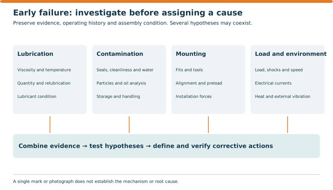
This is where tribology becomes central. Tribology studies friction, wear, lubrication and surface interaction. In rolling bearings, highly stressed contacts depend on a thin lubricant film and good cleanliness. Small deviations can trigger premature damage.
What is inside a rolling bearing?
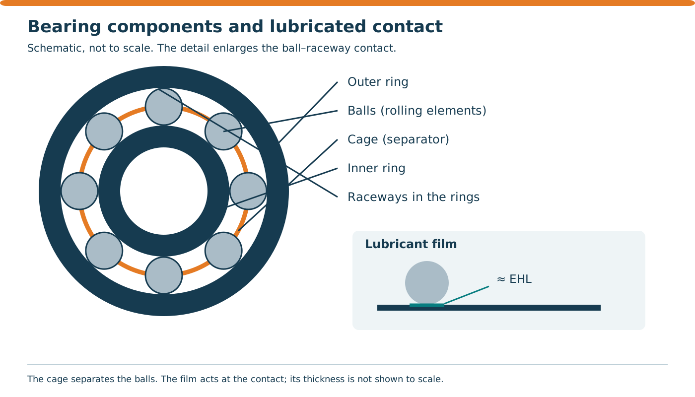
Inner ring, outer ring, rolling elements and cage function together. Raceways are the contact surfaces on the rings; the cage maintains spacing and guides rolling elements as designed. The lubricant film separates surfaces under applicable operating conditions. Real contacts are not free from all sliding: rolling, small relative movements, speed and load effects coexist.
Lubrication supplies the required film and helps control contact, wear and corrosion. Engineered circulating-oil systems can also transport heat. Grease has limited cooling ability; excessive filling can increase churning and temperature. The component sketch is conceptual, not to scale and not a particular commercial bearing.
What L10 life actually means
L10 is the basic rating life. In simplified terms, it is the number of revolutions that 90% of a sufficiently large group of identical bearings should complete before the first sign of rolling contact fatigue under defined conditions.
For ball bearings: L10 = (C/P)^3
For roller bearings: L10 = (C/P)^(10/3)
Where: - C = basic dynamic load rating - P = equivalent dynamic load
Example for a ball bearing: - C = 35 kN - P = 7 kN - n = 1200 rpm
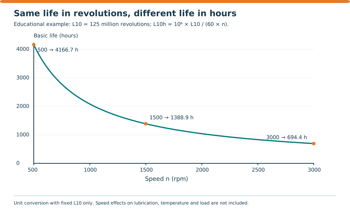
Then: - L10 = (35/7)^3 = 125 million revolutions - Life in hours ≈ 1,736 h
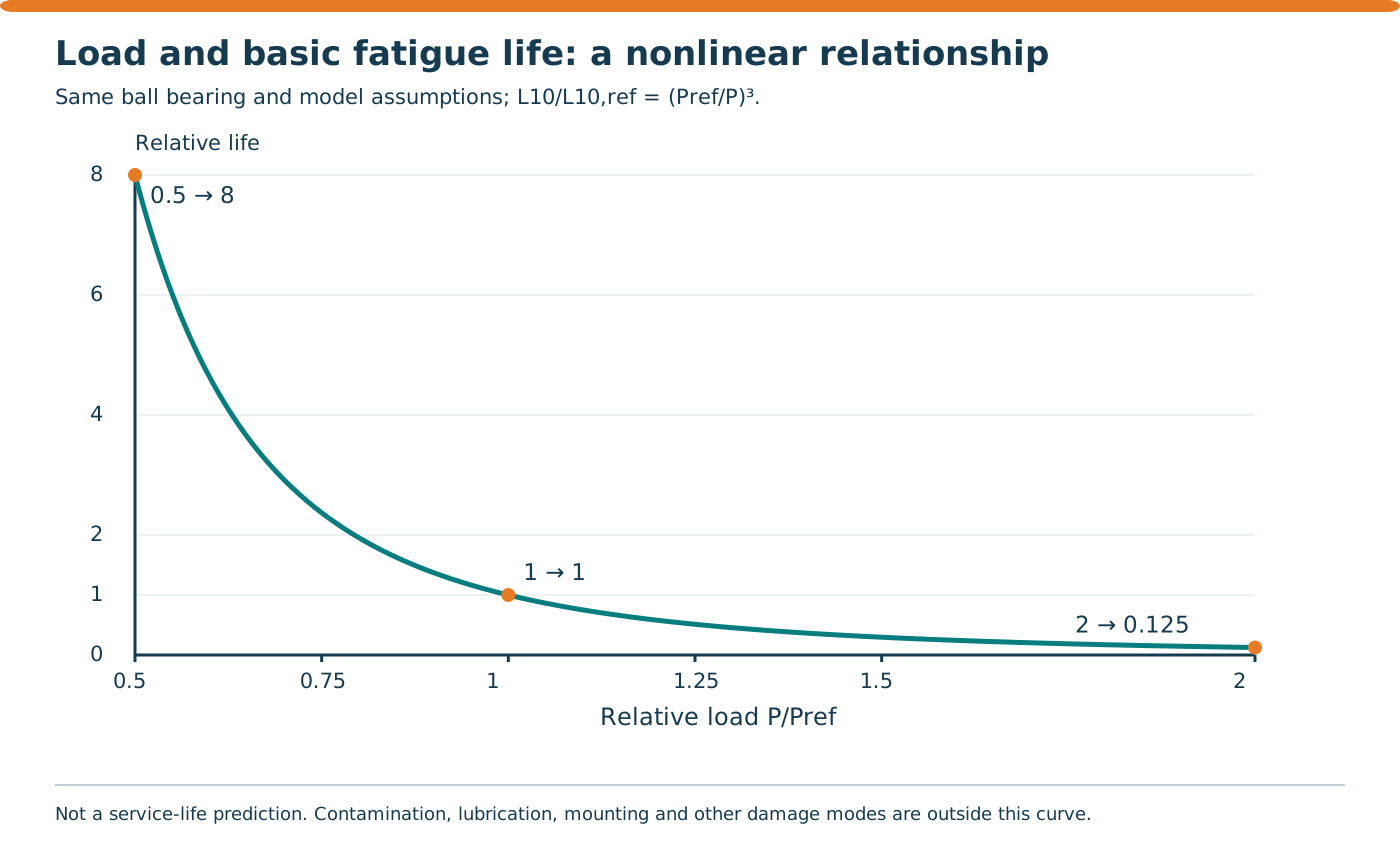
If load is halved to 3.5 kN: - L10 = 1000 million revolutions - Life ≈ 13,889 h
Life becomes 8 times longer. This shows how sensitive bearings are to load.
L10 is the basic rating life associated with 90% fatigue reliability for a population under defined conditions: statistically, 10% may develop fatigue damage earlier. It is not a 90% confidence interval, an updated individual probability or a warranty. An earlier failure therefore does not automatically prove a preventable installation or maintenance error; additional evidence is needed.
C is the selected bearing’s catalogue basic dynamic load rating. P is its equivalent dynamic load, determined for the arrangement and applicable radial/axial loading. Do not enter the total machine load without evaluating its distribution. C and P must use the same units. Preload, misalignment and contact-load distribution require application assessment; the example does not calculate those effects.
L10 = (C/P)^p in million revolutions, with p = 3 for balls and p = 10/3 for rollers. At constant n in rpm, L10h = [10⁶/(60·n)]·(C/P)^p in hours. C is not an allowable stress, and the dynamic calculation does not replace checks for static loads, shocks, speed or operating temperature.
For a secondary hypothetical roller example using the same C = 35 kN, P = 7 kN and n = 1,200 rpm, L10 = 5^(10/3) ≈ 213.747 million revolutions and L10h ≈ 2,968.71 h. At P = 3.5 kN, the results are approximately 2,154.435 million revolutions and 29,922.70 h: a factor of 2^(10/3) ≈ 10.079. This does not establish that replacing any ball bearing with any roller bearing provides that gain; actual ratings, geometry and application requirements differ.
On October 18, 2026, ISO 281:2007 remained the published edition, confirmed in 2021, with ISO/DIS 281 under development. Its public scope distinguishes basic and modified life; wear, corrosion and electrical erosion are outside the life model described there. This laboratory does not calculate modified life or additional lubrication, contamination and reliability factors. ISO 15243:2017 remains a published damage-classification reference; insufficient visual evidence calls for additional investigation.
| Type | P (kN) | p | L10 (million revolutions) | L10h (h) |
|---|---|---|---|---|
| Balls | 7 | 3 | 125 | 1,736.11 |
| Balls | 3.5 | 3 | 1,000 | 13,888.89 |
| Rollers | 7 | 10/3 | 213.747 | 2,968.71 |
| Rollers | 3.5 | 10/3 | 2,154.435 | 29,922.70 |
Laboratory: explore basic L10 life
Change C, P, speed and bearing type to explore equation sensitivity. Results are calculated basic lives under assumptions, not remaining life, service guarantees or permission to operate. The model does not diagnose lubrication, wear, corrosion or electrical erosion.
Laboratory — Basic bearing L10 rating life
Compare load and speed in an educational rolling contact fatigue model.
L10 is the basic fatigue rating life that 90% of a population of apparently identical bearings reach or exceed under reference conditions. It does not mean 90% remaining life and does not guarantee the life of an individual bearing.
L10 = (C/P)^p, in million revolutions. L10h = 10⁶ × L10 / (60 × n). p = 3 for ball bearings; p = 10/3 for roller bearings.
- L10 (million revolutions)
- 125
- L10h (hours)
- 1,736.111
- C/P ratio
- 5
- Exponent p
- 3
Scenario comparison
Basic rating life in hours for four scenarios; exact values appear in the table.
| Scenario | P (kN) | n (rpm) | L10 (million revolutions) | L10h (hours) | L10h / reference |
|---|---|---|---|---|---|
| Current reference | 7 | 1,200 | 125 | 1,736.111 | 1× |
| Half load P | 3.5 | 1,200 | 1,000 | 13,888.889 | 8× |
| Double load P | 14 | 1,200 | 15.625 | 217.014 | 0.125× |
| Double speed n | 7 | 2,400 | 125 | 868.056 | 0.5× |
CSV: educational model with inputs, results and limitations; no integrity assessment.
This model assumes constant equivalent load and speed. Obtain P from the catalogue for the load combination and bearing type; it is not automatically the measured radial load. C and P use the same unit. Minimum load, static load, speed limits, temperature, installation, lubrication, contamination and modified rating life are not assessed.
Basic rating life does not diagnose failure causes, calculate remaining life, set a replacement interval or approve equipment for operation.
Main reasons for premature failure
1. Inadequate lubrication
Wrong viscosity, insufficient lubricant, excessive grease, thermal degradation or poor relubrication intervals can reduce film thickness and increase wear, heat and smearing.
Selection depends on viscosity at operating temperature, speed, load, compatibility, sealing and supply method. Mixing products without assessment or imposing one relubrication interval on all applications can introduce problems. Heating requires examination of lubricant quantity and condition alongside other causes; automatically adding grease is neither a diagnosis nor a guaranteed remedy.
2. Contamination
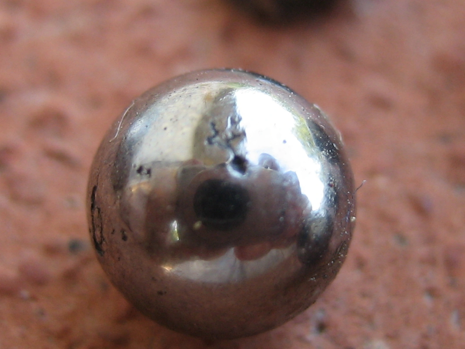
Solid particles and water can dent raceways, degrade lubricant and create local stress concentrations that accelerate spalling.
Particle indentations can create stress concentrations and accelerate damage. Water can also contribute to lubricant degradation and corrosion. Examine seals, environment, storage, handling, tool cleanliness and lubricant analysis. Subsequent running may enlarge the original damage, so the removed bearing need not preserve the complete event sequence.
3. Poor mounting and adjustment
Improper fits, incorrect mounting force, misalignment and preload errors can create permanent damage before service even starts.
Mounting force should follow the fit and manufacturer’s procedure, avoiding inappropriate transmission through rolling elements. Record tools, method, fits, clearance/preload and alignment to test hypotheses. Repeated replacement without checking the shaft, housing and load path can leave the damage-producing condition in place.
4. Overload and severe operating conditions
Shock loads, vibration, electrical current, high temperature and persistent contamination can all shorten life.
Lower load is not an unlimited benefit: excessively light loading can encourage sliding in some applications. The eightfold result describes the basic equation only; it does not verify minimum load, skidding, speed limits or film behaviour. Actual selection must respect the operating envelope and manufacturer’s guidance.
Common damage modes
Appearance guides damage classification; causes need correlation with history and application conditions.
ISO 15243:2017 — public scope →
Timken — Bearing Damage Analysis →
- Spalling: Local material loss can arise from subsurface or surface-initiated fatigue, contamination, poor lubrication or concentrated stress; it does not prove natural end of life.
- Abrasive wear: Scratches, polishing and material removal can support a particle-contamination hypothesis; identify contaminants and their origin.
- Smearing / adhesive wear: Material transfer or dragging associated with sliding, film disruption and local heat; not simply too little grease.
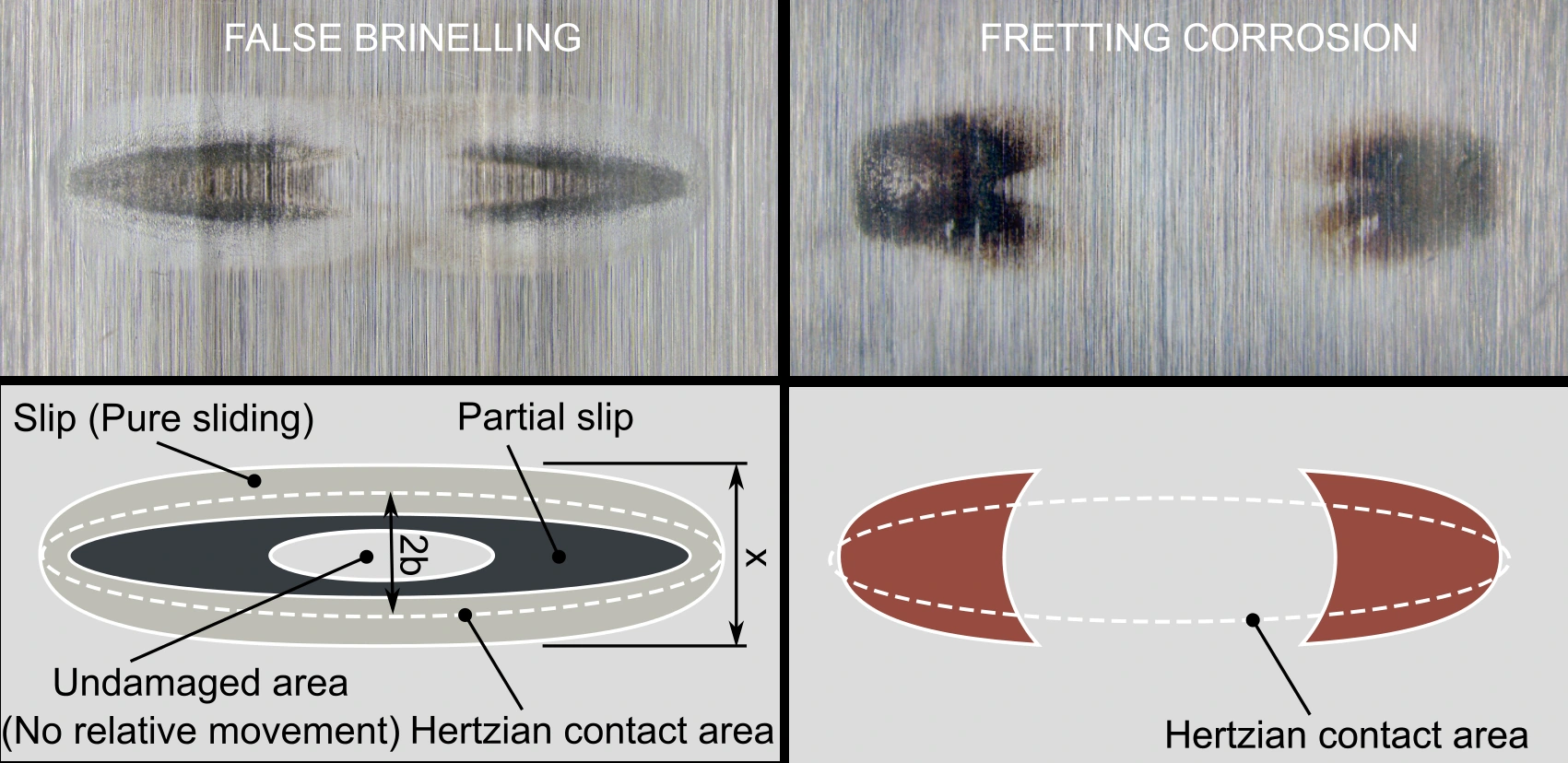
- True brinelling: Plastic indentations from static overload or shock; investigate loading and handling.
- False brinelling: Localized wear from small oscillations, often at standstill; distinct from plastic indentation.
- Corrosion / etching: Attack associated with moisture or chemicals; preserve fluid and exposure evidence.
- Electrical erosion: Microcraters and periodic fluting support an electrical hypothesis; confirm electrical context and additional evidence.
- Cage damage: Wear, deformation or fracture needs assessment of the assembly, lubrication, installation and loading.
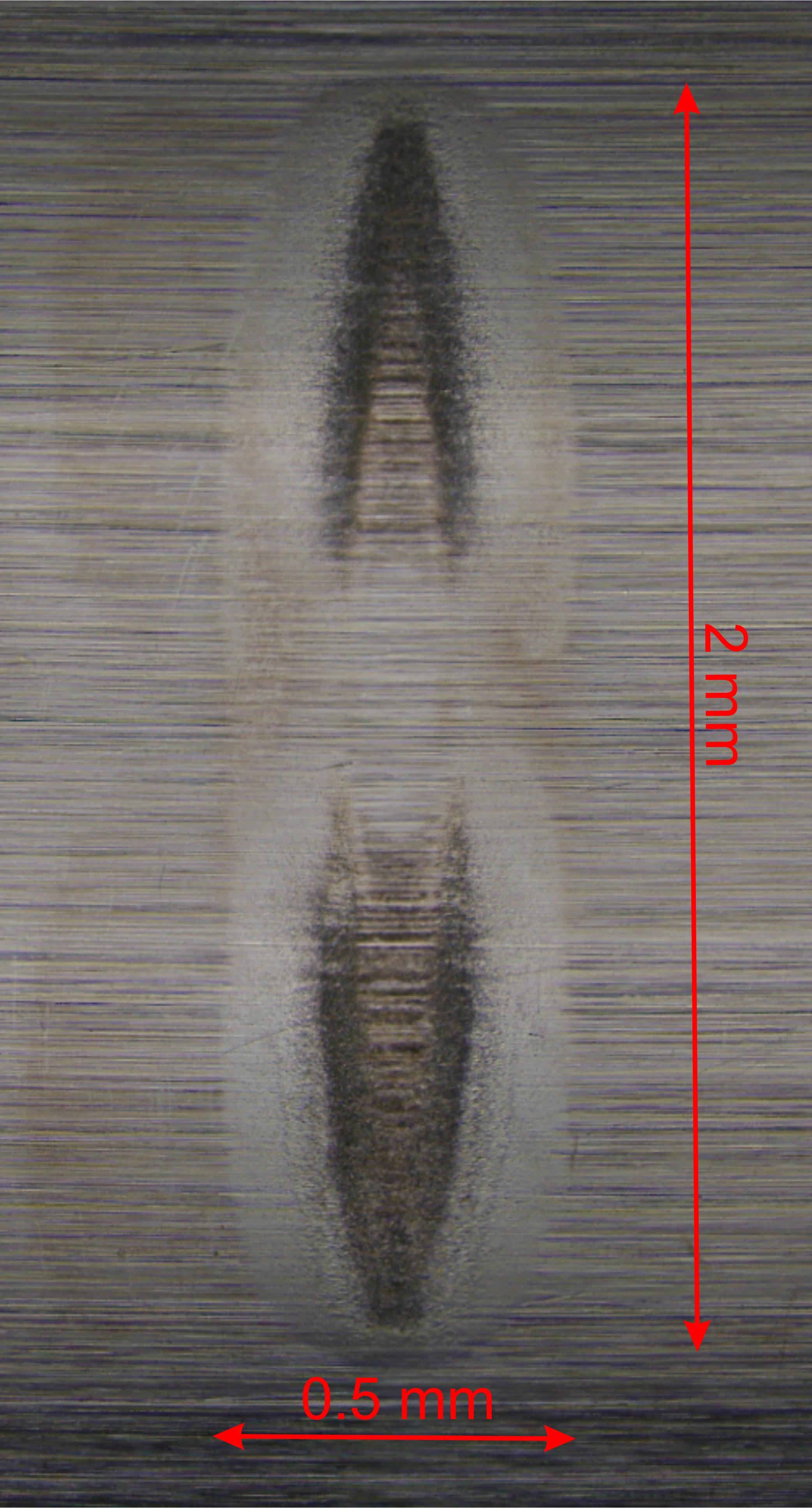
Diagnosis: observation, hypothesis and verification
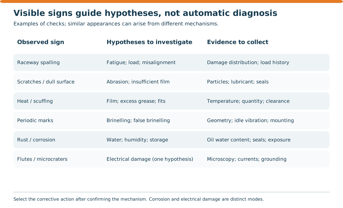
These relationships guide hypotheses rather than automatic diagnosis. Record mounting position, load orientation, raceways, elements, cage and lubricant before changes destroy evidence. Removal and inspection require planning and control of machine energy.
| Observed symptom | Possible hypothesis | What to inspect | Action after confirmation |
|---|---|---|---|
| Localized spalling | Fatigue or accelerated surface-related damage | Load pattern, dents, film and history | Correct the demonstrated cause and review selection/application. |
| Scratches and particles | Contamination / abrasive wear | Seals, lubricant, tools and storage | Correct ingress and verify cleanliness. |
| Heat and smeared surfaces | Film, churning, sliding or loading problems | Viscosity, fill, speed, fits and loads | Adjust confirmed lubrication/application conditions. |
| Spaced marks | Plastic indentation or oscillatory wear | Morphology, transport, stoppages, shocks and mounting | Address the identified mechanism; spacing alone is insufficient. |
| Microcraters / fluting | Possible electrical erosion | Power supply, drive, currents and electrical paths | Specify measures with specialists for the actual system. |
| Rust / etching | Water or chemical exposure | Seals, storage and fluid analysis | Control ingress/exposure and review preservation. |
Predictive maintenance perspective
Vibration analysis, temperature trending, ultrasound, lubricant inspection and maintenance history can help distinguish natural fatigue from accelerated failure mechanisms.
Compare vibration and temperature trends under known operating conditions instead of treating one peak as a diagnosis. Defect-related frequencies depend on geometry, speed and contact conditions; vibration alone does not identify one root cause. Ultrasound, water/particle analysis and relubrication records add evidence. Avoid universal temperature limits or maintenance intervals without the application and manufacturer’s requirements.
Conclusion
A failure before calculated life deserves investigation, not automatic blame of component quality or maintenance. Application conditions may accelerate damage, and fatigue life itself has statistical scatter. Reliability improves when sealing, lubrication, selection, mounting and monitoring are treated as one system, with action effectiveness verified.
Connecting calculations to the machine
Metal fatigue provides context for cyclic loading and damage propagation without replacing bearing-specific relationships. Vibration and resonance help assess assembly loads and interpret field signals. Accident investigation beyond blame, in Portuguese, reinforces the distinction between evidence, hypotheses and confirmed causes.
Laboratory and study resources
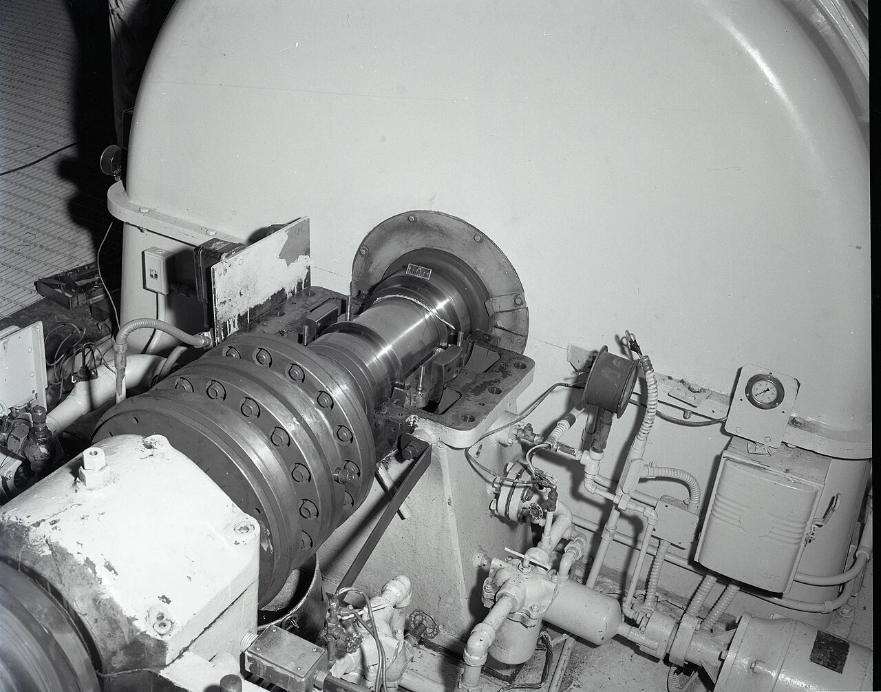
Editorial review: October 18, 2026. Archival photographs have their own context and damage history; they do not represent an Andrade Safe case. Diagrams are educational. Estimates do not replace manufacturer selection, application assessment or field diagnosis.
Open standalone laboratory — PT/EN/ES →
Download educational scenarios and calculations CSV →
Download revised kit with articles, figures and credits →
Donald Huebler / NASA, via NARA (NAID 17469411) — Public domain (NASA / US federal work) →


Fabian Schwack — CC BY-SA 4.0 →

Felix Prigge, Fabian Schwack, Artjom Byckov — CC BY-SA 4.0 →

Primary sources and public scopes
NSK — Dynamic Load Ratings and Fatigue Life →
SKF — Golden opportunities, damage analysis →
SKF — Grease lubrication mechanisms →
SKF — Prevention of electric erosion →
Frequently asked questions
Is L10 a guaranteed bearing life?
No. It is a basic fatigue life associated with 90% reliability for a population under defined conditions, not a warranty for an individual bearing.
Can C and P use different units?
No. C/P requires consistent units, for example both in kN. P must be the bearing’s equivalent dynamic load rather than an arbitrary machine load.
Does halving load always increase life eightfold?
The basic ball-bearing equation gives that factor with other assumptions held constant. It does not check minimum loading, sliding, temperature, lubrication or real selection. The roller factor is approximately 10.079.
Does spalling prove normal end-of-life fatigue?
No. Spalling may follow several sequences and accelerating conditions; damage patterns and history require investigation.
Are true and false brinelling the same?
No. True brinelling is plastic indentation from load/shock; false brinelling is wear from small oscillations. Both may show spaced marks.
Is electrical damage the same as moisture corrosion?
No. Electrical erosion and corrosion are distinct mechanisms requiring specific evidence and measures.
Does more grease solve overheating?
Not necessarily. Excess grease can increase churning and heat; investigate the causes of heating.
Does the lab predict a replacement date?
No. It illustrates basic rating-life equations, without diagnosis or individual failure prediction.