
Learn how salt spray and moisture promote steel corrosion, how thickness loss is assessed, and what controls protect coastal metal structures.
What is marine corrosion?
Marine corrosion is material deterioration caused by interaction with a coastal or seawater environment. On steel, moisture, deposited salts and oxygen support electrochemical processes; chlorides, wet/dry cycles and detailing influence the attack. Visible rust alone does not establish load capacity. Assessment must identify the mechanism, measure the damage and evaluate the component in its actual structural context.
Rust on a seaside railing is easy to spot. What is harder to determine is whether the underlying steel has lost enough material to affect structural performance. Visual appearance alone cannot reveal the remaining strength of a fastener, connection or support. A sound assessment asks what corrosion mechanism is active, where it is occurring and what it changes about the component.
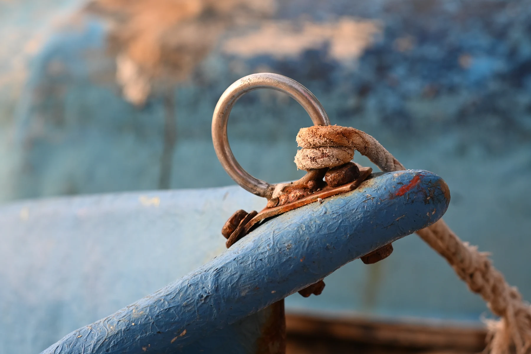
Salt spray and the electrochemical process
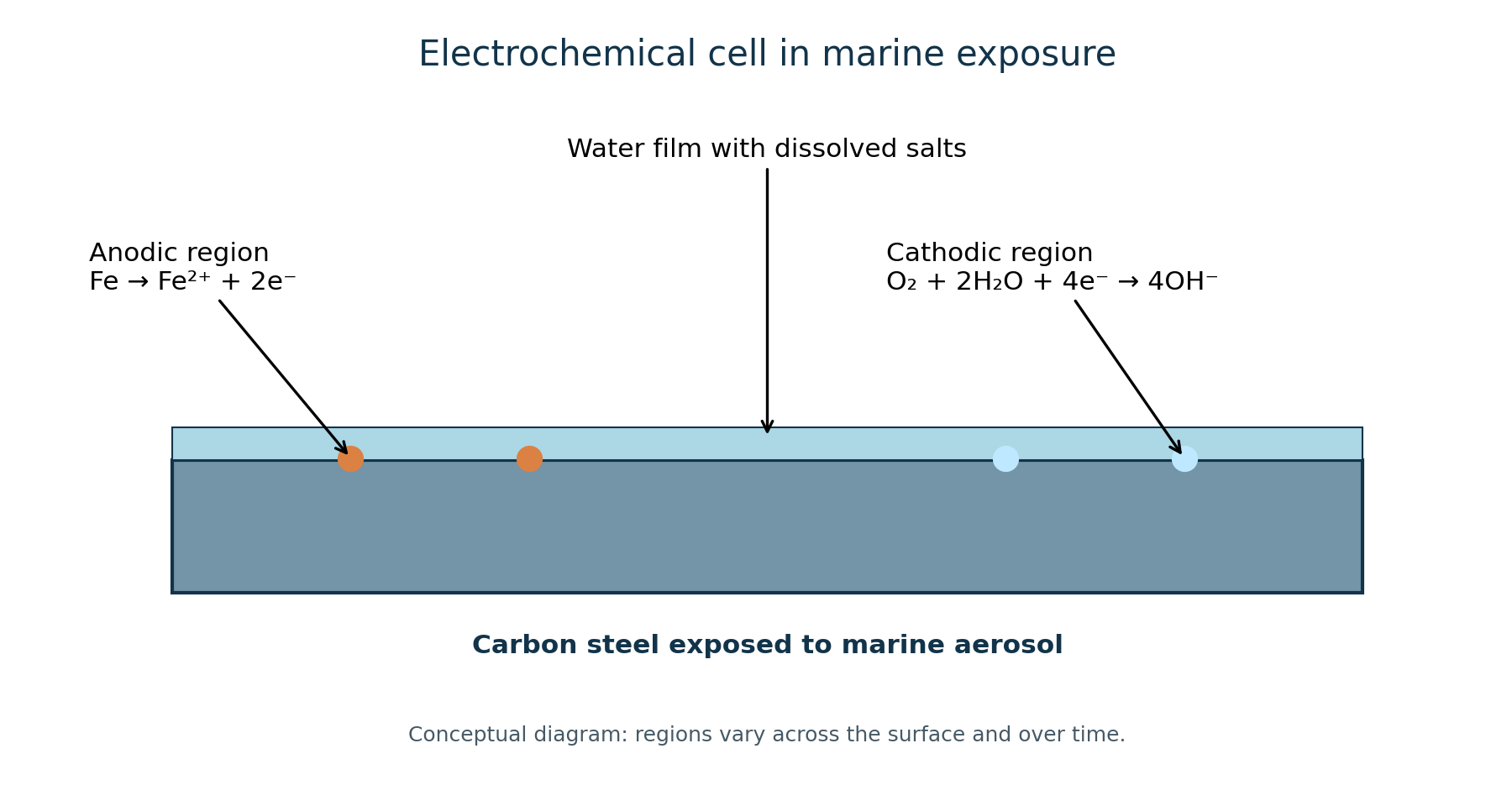
Carbon steel can corrode in a conductive film of moisture. Along the coast, airborne saline droplets deposit chlorides, influencing electrolyte conductivity and the behavior of protective surface films. Oxygen availability, temperature, time of wetness, wet/dry cycles and detailing all affect the process. A conceptual anodic reaction is Fe → Fe²⁺ + 2e⁻; a common cathodic reaction in aerated water is O₂ + 2H₂O + 4e⁻ → 4OH⁻.
Corrosion severity cannot be predicted from distance to the shoreline alone. Wind exposure, rain-washing, shelter, local topography and the accumulation of salts in crevices can create striking differences even within the same facility. FHWA guidance on coastal weathering steel describes why site-specific evaluation matters.
Distinct corrosion mechanisms
Uniform corrosion reduces thickness over a relatively large area. Pitting corrosion produces localized cavities that may become deep despite modest total mass loss. Crevice corrosion can develop at joints, lap connections and sheltered contact surfaces. Galvanic corrosion requires electrically connected dissimilar metals and a common electrolyte; it depends on material selection and geometric conditions. Coating underfilm corrosion and corrosion near weld details should be evaluated separately when relevant.
This distinction is essential: a severely discolored plate is not necessarily the weakest component, while hidden corrosion in a bolt or connection may be more consequential than surface staining suggests. Stainless steel is not universally immune to chloride-related damage.
Galvanic corrosion requires electrical coupling and a shared electrolyte; physical proximity alone is insufficient. Relative areas matter: a small anodic region connected to a large cathodic area can suffer concentrated attack. Material selection and isolation must account for electrical continuity, retained moisture and the durability of the chosen detail.
In reinforced concrete, chlorides can disrupt reinforcement passivity; corrosion and its products can contribute to cracking and cover spalling. This is a related but distinct case involving transport through concrete, cover and its own assessment methods. The plate calculation does not evaluate a concrete slab or anchor. Underfilm attack and welded details also need separate mapping rather than an assumption of uniform loss.
The role of standards
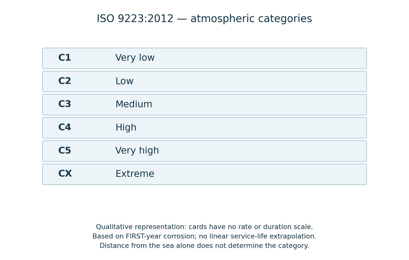
ISO 9223:2012 classifies atmospheric corrosivity from C1 to CX, based on first-year corrosion performance of reference metals and/or environmental estimation. ISO 12944-2:2017 describes environments relevant to protective coating systems. Atmospheric exposure must not be confused with immersion or splash-zone service. A first-year category is not a universal long-term loss rate for an actual steel member.
On October 18, 2026, ISO 9223:2012 remained current, confirmed in 2022. ISO 12944-2:2017 was still the published edition, confirmed in 2023, with revision planned and a successor under development. ASTM G1-25 was active. Public catalogues and scopes were consulted; this does not mean every clause of the full standards was reviewed.
C5 and CX are atmospheric categories, not automatic labels for every building near a beach. No category is assigned to João Pessoa or an individual façade from its address alone. Standard estimates and reference tests have defined conditions; first-year loss on reference metal does not directly describe a coated member, a deep pit or an old connection.
Worked example: thickness loss and nominal stress
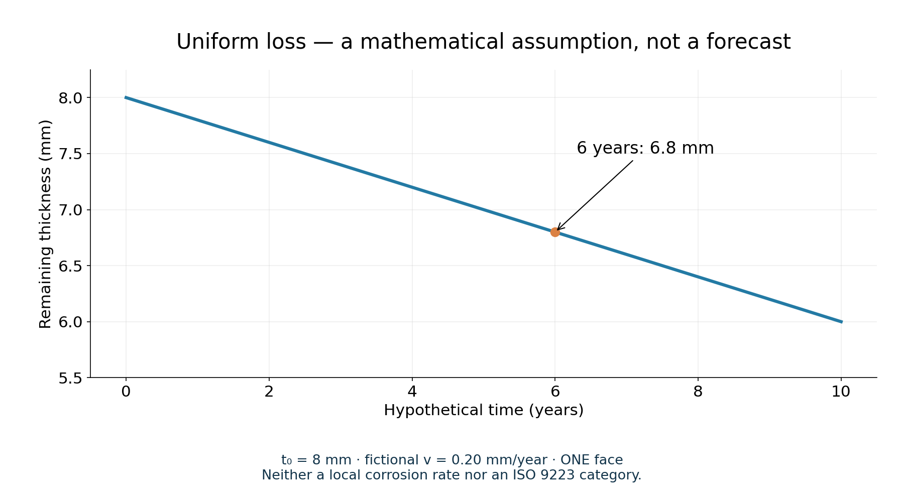
Consider a fictional plate, 100 mm wide and 8.0 mm thick, exposed to a supposed uniform loss of 0.20 mm per year on one face for six years. The rate is chosen for teaching only and is not a measured or typical value for any particular coast.
Remaining thickness: 8.0 − (0.20 × 6) = 6.8 mm. The cross-sectional area decreases from 800 mm² to 680 mm²: a 15.0% reduction. Under a fixed ideal axial force of 80 kN, average tensile stress rises from 100 MPa to 117.65 MPa, a 17.65% increase.
This arithmetic does not demonstrate structural safety or failure. It ignores connections, welds, eccentricity, bending, buckling, local pits and actual material characteristics. Corrosion on two faces would require a different thickness model. For a hypothetical Ø12 mm bar with uniform radial penetration of 0.6 mm, the remaining Ø10.8 mm section has 19% less area, and fixed-load nominal stress increases by 23.46%.
The exercise assumes pure axial tension acting through the remaining section’s centroid. Uniform loss on one face moves that centroid; retaining the original force line can introduce eccentricity and bending. F/A isolates the area effect and excludes this additional action. Width remains fixed and the example has no holes, notches or connection-related net-section reduction.
The model uses t = t₀ − n·v·a: t and t₀ are thicknesses in mm, n is the number of faces (1 or 2), v is hypothetical penetration per face in mm/year and a is duration in years. A = b·t in mm²; σ = 1,000·F/A in MPa for F in kN. With the same assumed penetration on two faces, t = 5.6 mm, A = 560 mm², area loss is 30% and σ ≈ 142.86 MPa: a 42.86% stress increase, not 30%.
| Condition | t (mm) | A (mm²) | σ (MPa) | Area / stress change |
|---|---|---|---|---|
| Initial | 8.0 | 800 | 100 | — |
| One face | 6.8 | 680 | 117.65 | −15% / +17.65% |
| Two faces | 5.6 | 560 | 142.86 | −30% / +42.86% |
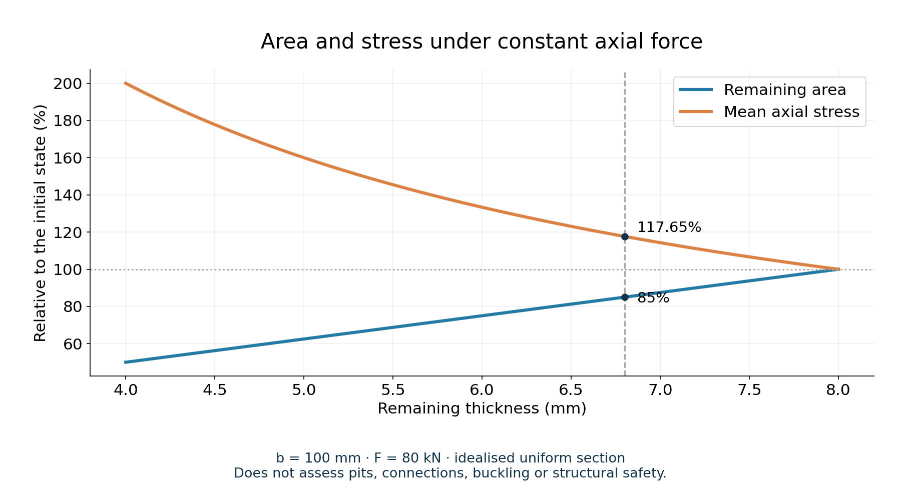
Laboratory: remaining section and nominal stress
Change dimensions, duration, force and face count only to explore the assumptions. The 0.20 mm/year rate is fictional: it is not a João Pessoa measurement, ISO class value or typical coastal rate. The panel gives no approval, collapse classification or remaining life. Pits, welds, connections, bending, buckling and mechanical properties require separate assessment.
Marine corrosion: geometric section loss
Explore an assumed uniform thickness loss in a flat plate under ideal axial loading. Educational mathematics only — not an integrity assessment.
Hypothetical parameters
The rate is an assumed input to illustrate mathematics. It is not a typical João Pessoa rate, field measurement, ISO 9223 category or service-life prediction.
Model results
Uniform-loss model under a constant centered axial force. Excludes pits, welds, connections, buckling, bending, eccentricity, material properties and strength criteria. It determines neither failure nor remaining life nor a safe/unsafe condition. The force acts through the remaining centroid; one-face loss with a fixed load line can introduce bending.
Hypothetical geometric projection
A straight line is not a corrosion forecast: mechanisms and rates can change over time.
Equations used
t = t₀ − n × v × Δt; A = b × t; σ = F / A
F [kN] × 1000 → N; N/mm² = MPa.
Curve values (selection)
| Years | Remaining thickness (mm) | Remaining area (mm²) | Final nominal stress (MPa) |
|---|---|---|---|
| 0 | 8 | 800 | 100 |
| 1.05 | 7.79 | 779 | 102.7 |
| 2.1 | 7.58 | 758 | 105.54 |
| 3.15 | 7.37 | 737 | 108.55 |
| 4.2 | 7.16 | 716 | 111.73 |
| 5.25 | 6.95 | 695 | 115.11 |
| 6.3 | 6.74 | 674 | 118.69 |
| 7.35 | 6.53 | 653 | 122.51 |
| 8.4 | 6.32 | 632 | 126.58 |
References and limits
ISO 9223 concerns atmospheric corrosivity classification; it does not supply this exercise’s assumed rate. F/A is nominal stress, not a strength verification. ISO 9223:2012.
Why does a straight graph not predict service life?
Constant loss is a mathematical assumption. Wetting, deposits, corrosion products, coating deterioration, interventions and localized attack can change actual progression. The graph does not convert a first-year test into a forecast for decades. If calculated thickness reaches zero or becomes negative, the model’s domain is exhausted: no positive area exists for F/A. This is not a predicted rupture date.
Inspecting a coastal structure
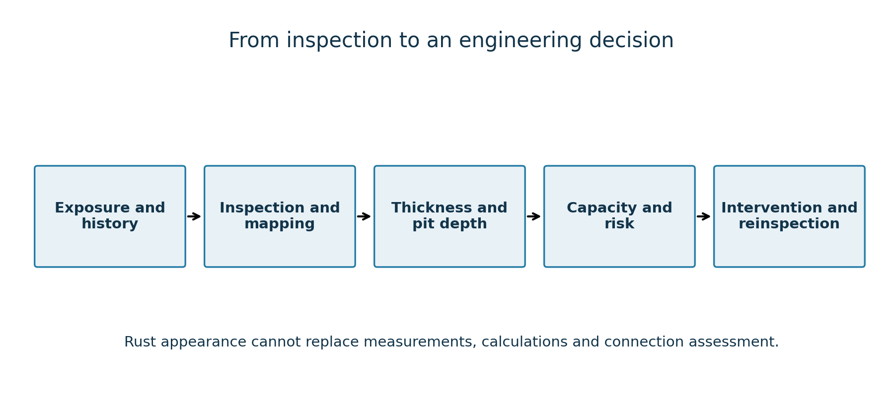
A professional assessment begins with environmental and maintenance history. Photographs should include scale, orientation and an exact location on the asset. Inspectors then look for coating breakdown, moisture traps, crevice geometry, fasteners, anchors, welded details and accessible remaining dimensions. Suitable calibrated methods are used to measure thickness or localized attack. Engineering assessment compares measured sections with drawings, load paths, requirements and relevant limit states.
ASTM G1-25 addresses preparation, cleaning and evaluation of laboratory corrosion specimens. It should not be misrepresented as a universal field-inspection procedure. Where loose components or suspect connections pose immediate hazards, access controls and urgent specialist assessment may be warranted.
Measurement records should state method, instrument, calibration, surface preparation, grid and location, including the ability to detect relevant minimum thickness. Coatings and corrosion products can affect readings. Ultrasound or suitable dimensional methods must fit access and geometry; mean thickness cannot replace characterization of pits, crevices and remaining ligaments. Uncertainty about the original section must remain explicit when drawings or reliable initial dimensions are unavailable.
Managing corrosion instead of repainting symptoms
Solutions include avoiding water traps, ensuring drainage, specifying suitable coatings and surface preparation, considering hot-dip galvanizing or duplex systems, selecting appropriate alloys, separating problematic galvanic couples and scheduling inspection. Cathodic protection can be appropriate for certain submerged or buried assets but is not a one-size-fits-all answer for exposed balconies and railings. Repainting over a damaged fastener does not restore metal that has been lost.
Maintenance introduces its own occupational and environmental risks: work at height, falling material, abrasive preparation, airborne dust, coatings and waste management. Controls must be appropriate to the actual task and surroundings.
Repainting does not restore lost metal. A coating specification should address surface preparation, residual salts, profile, application conditions, dry-film thickness and repairs. The FHWA coating-performance publication reports bridge research; it is not a universal recipe for railings or bolts. Historical weathering-steel guidance also cannot be generalized to every alloy or treated as Brazilian law.
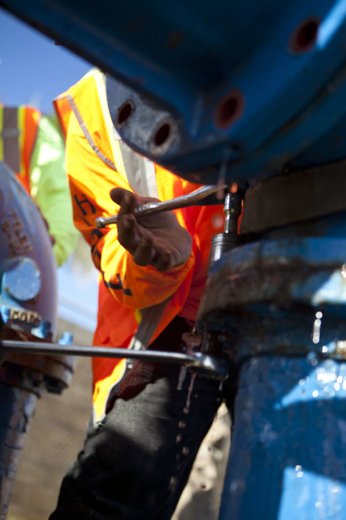
Cathodic protection requires a suitable electrochemical circuit and engineered design, including specific reinforced-concrete applications. The archival Hawaiian pipeline-maintenance photograph illustrates its own protection context; it does not establish suitability for an atmospheric member. Galvanizing, duplex systems and stainless steels likewise require compatible specifications and maintenance.
Monitor, repair, strengthen or replace?
The choice combines the element’s function, failure consequences, extent and location of loss, available evidence and design verification. This article gives no universal acceptable-loss percentage. Before selecting an intervention, distinguish restoring a protective coating from restoring load capacity and define how the result will be verified.
| Option | When to consider it | What must be demonstrated |
|---|---|---|
| Monitor | After assessment supports continued service | Measurement locations, criteria and reinspection plan/interval. |
| Repair protection | Coating is deteriorated and the substrate has been assessed | Preparation, specification and application quality; paint does not restore section. |
| Strengthen | Engineering verification identifies the need | Design, load path, connections and compatible execution. |
| Replace | Technical criteria show inadequacy or impractical repair | Specification, installation and verification of the new component. |
Conclusion
Marine exposure turns the environment into a design and maintenance variable. Strong decisions rely on electrochemistry, accurate inspection, structural evaluation and a defensible maintenance strategy — not on the color of rust alone.
Connections with other damage mechanisms
Metal fatigue explains cyclic cracking; corrosion may change that response and needs its own evidence, rather than adding simplified models as though they were interchangeable. Hydrogen embrittlement involves different mechanisms and cannot be diagnosed from rust alone. Metal creep concerns time-dependent deformation, particularly at elevated temperature. Vibration and resonance belong in the assessment of loads and connections.
Laboratory and study data
Technical review: October 18, 2026. Archival photographs have their own authorship, date and context; they do not show the fictional plate or a Brazilian project. Figures are educational. This material is not a structural assessment, execution design or authorization for use.
Open standalone laboratory — PT/EN/ES →
Download educational scenarios with explicit assumptions →
Sources and consulted scopes
ISO 9223:2012 — atmospheric corrosivity →
ISO 12944-2:2017 — classification of environments →
FHWA — Uncoated Weathering Steel in Structures →
FHWA-HRT-20-065 — coating performance, September 2020 →
AMPP — Maritime Corrosion Prevention →
AMPP — Common marine coating problems →


Frequently asked questions
Does visible rust prove loss of load capacity?
Not by itself; measurement and engineering checks are necessary.
Is galvanized or stainless steel immune to sea spray?
No material provides unconditional immunity; exposure and specification determine suitability.
Can a single corrosion rate predict service life?
Not reliably for a real component without supporting data, especially where localized attack is present.
Does distance from the coast determine ISO corrosivity class?
Not on its own.
What is marine corrosion?
Material deterioration arising from interaction with a coastal or seawater environment; moisture, salts, oxygen and local conditions affect electrochemical processes in metals.
How do uniform, pitting and galvanic corrosion differ?
Uniform attack distributes loss; pitting concentrates it in cavities; galvanic attack involves electrically coupled materials sharing an electrolyte. Diagnosis needs material, exposure and damage-distribution evidence.
How is thickness loss measured in a steel structure?
Use methods and calibrated instruments suited to geometry and surface condition, mapping thickness and local attack. Relate measurements to drawings, tolerances, loads and engineering checks.
References
- ISO 9223:2012 — atmospheric corrosivityISO
- ISO 12944-2:2017 — classification of environmentsISO
- ASTM G1-25 — public scopeASTM International
- FHWA — Uncoated Weathering Steel in StructuresFHWA
- FHWA-HRT-20-065 — coating performance, September 2020FHWA
- AMPP — Maritime Corrosion PreventionAMPP
- AMPP — Galvanic CorrosionAMPP
- AMPP — Cathodic ProtectionAMPP
- AMPP — Common marine coating problemsAMPP