
Learn how hydrogen embrittlement affects ductility and cracking, with diffusion models and a 2026 study on nickel alloy 725.
What is hydrogen embrittlement?
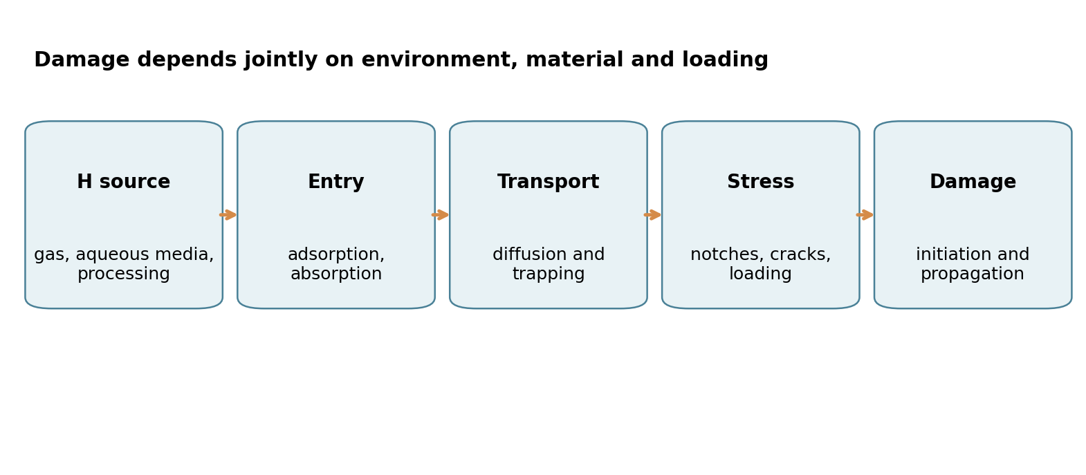
Hydrogen embrittlement describes phenomena in which hydrogen absorbed by a metal can reduce ductility and promote cracking. It depends on the interaction of material and microstructure, hydrogen availability, and static or cyclic stress. High tensile strength alone does not ensure resistance to hydrogen-assisted fracture.
A material may have high tensile strength yet develop cracks prematurely when hydrogen, its microstructure, and mechanical stresses interact. Hydrogen embrittlement describes several phenomena in which hydrogen in a metal can affect ductility, localized deformation and fracture. It is not the same thing as visibly corroded metal, and susceptibility is not identical among alloys.
A paper published on 12 October 2026 in the Journal of Materials Research illustrates why this subject is so complex. Researchers compared the response of nickel-based alloy 725 after introducing hydrogen using two different methods. Their main finding was not that one method is invariably dangerous, but that total hydrogen content alone cannot reliably explain where cracks form.
High strength does not guarantee crack resistance
Strength, ductility and fracture toughness describe related but distinct properties. For hydrogen-exposed components, the operating environment, residual stress, applied and cyclic loads, surface condition, welding, heat treatment and microstructure can alter the damage response. A delayed crack is not proof of hydrogen embrittlement unless competing mechanisms have been assessed.
How hydrogen enters a metal
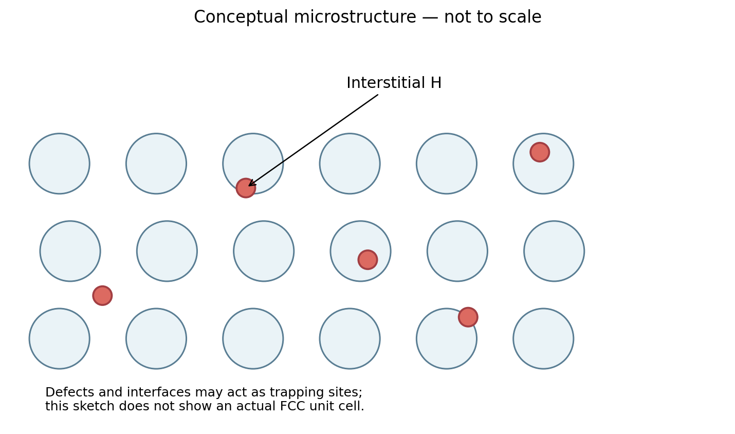
Molecular hydrogen gas (H2) outside a component is different from atomic hydrogen absorbed in the metallic lattice. Hydrogen can enter through certain manufacturing or coating processes, electrochemical reactions in aqueous environments, or surface adsorption and dissociation under gaseous exposure. Once absorbed, atoms may diffuse and interact with dislocations, vacancies, interfaces, grain boundaries and precipitates, sometimes becoming trapped.
Research often discusses HEDE (hydrogen-enhanced decohesion), involving altered local bonding resistance, and HELP (hydrogen-enhanced localized plasticity), involving localized movement of dislocations. Neither model alone should be presented as a universal explanation; hydrogen-assisted failure is highly dependent on alloy, loading and exposure conditions.
What the 2026 alloy 725 study observed
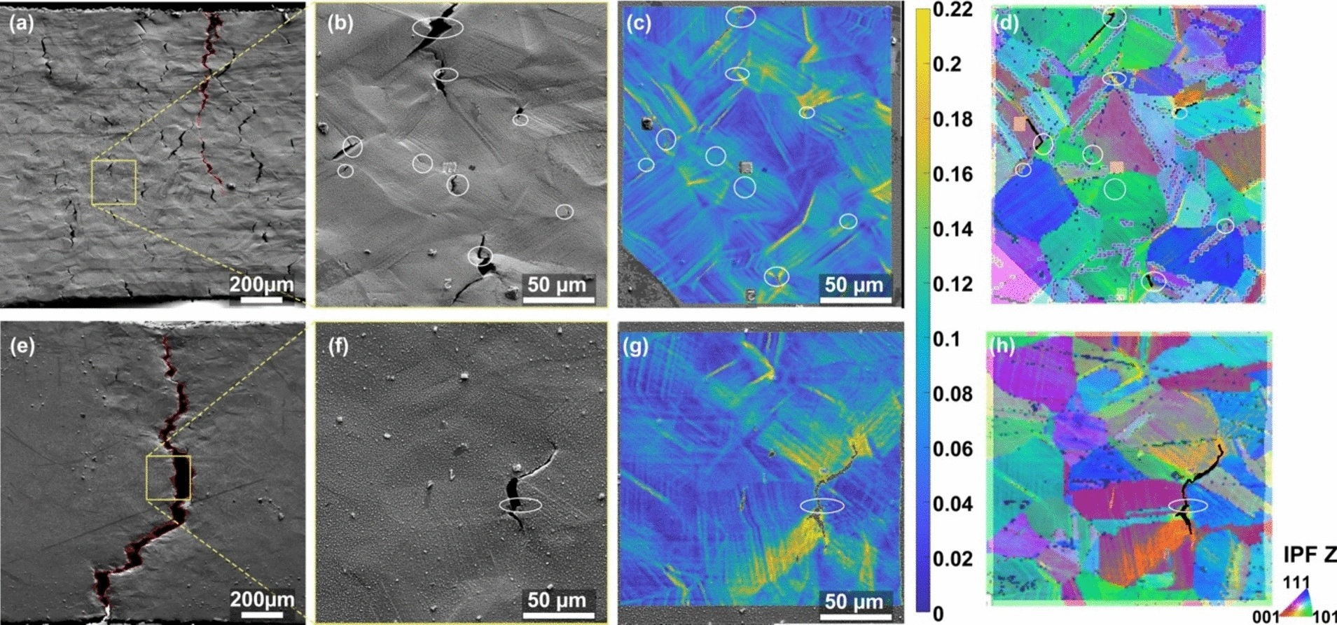
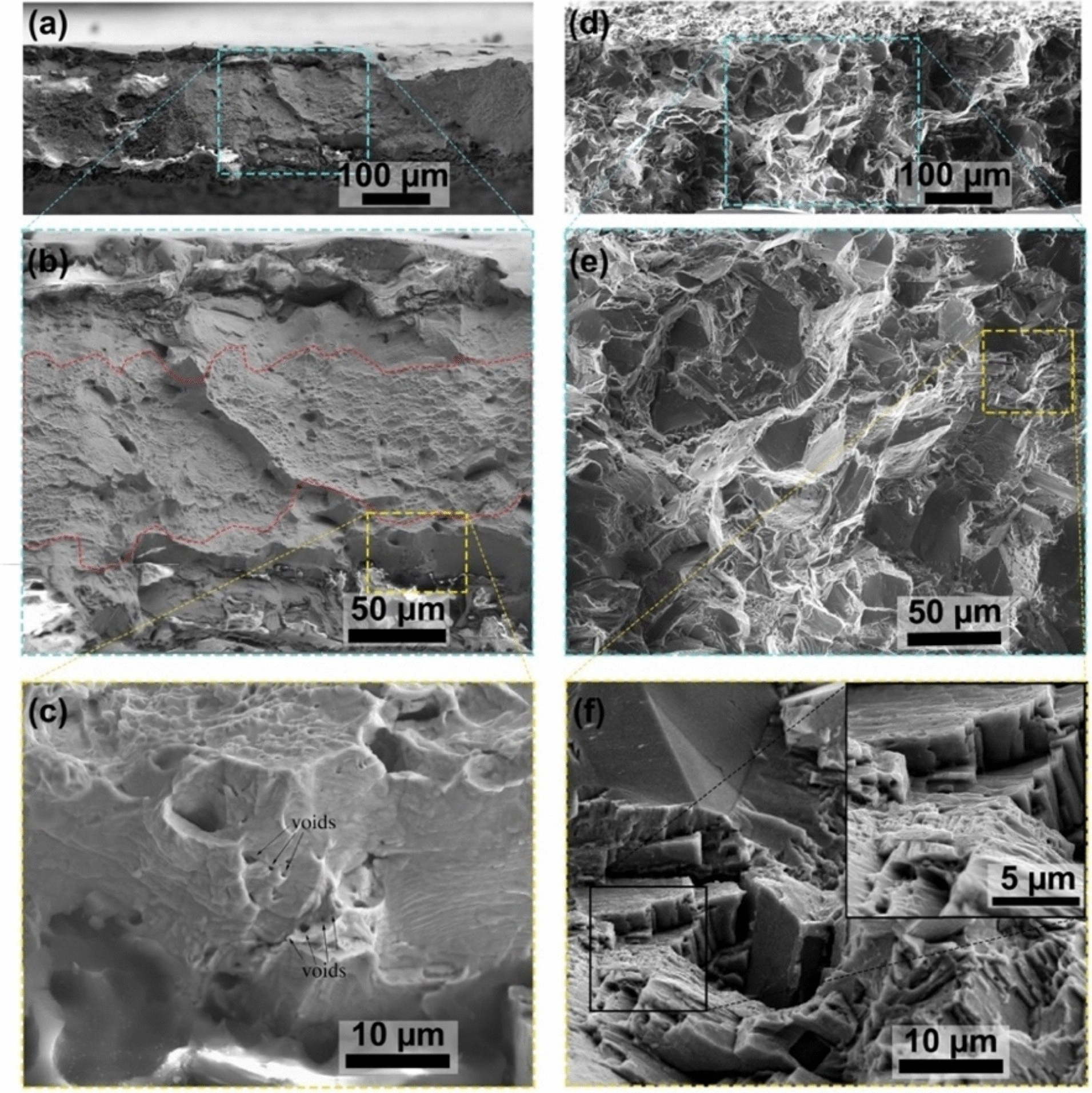
Mengying Liu and colleagues investigated a high-strength, face-centered cubic (FCC) nickel alloy. They compared electrochemical pre-charging with high-pressure, elevated-temperature gaseous pre-charging, then studied slow tensile testing. Scanning electron microscopy (SEM), digital image correlation (DIC), electron backscatter diffraction (EBSD), fractography and X-ray computed tomography revealed where damage occurred.
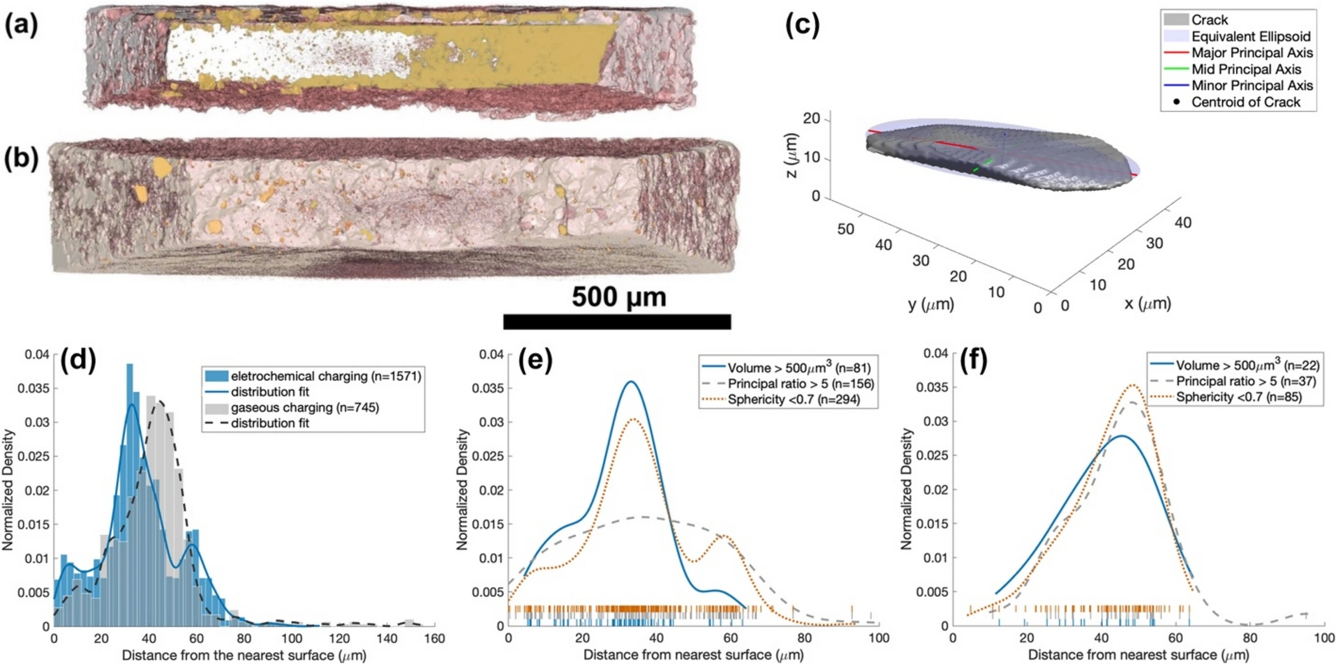
CT identified 1,571 defects in the electrochemical condition and 745 in the gaseous condition, but two fractured halves were scanned in the first case and only one in the second; deformation also changed the cross-section. These totals cannot rank relative damage severity. The relevant comparison concerns normalized depth distributions: defects concentrated near 30–40 µm after electrochemical charging and a peak around 40–60 µm after gaseous charging. Segmented defects include cracks, voids and inclusions; the authors used geometric criteria to select crack-like defects.
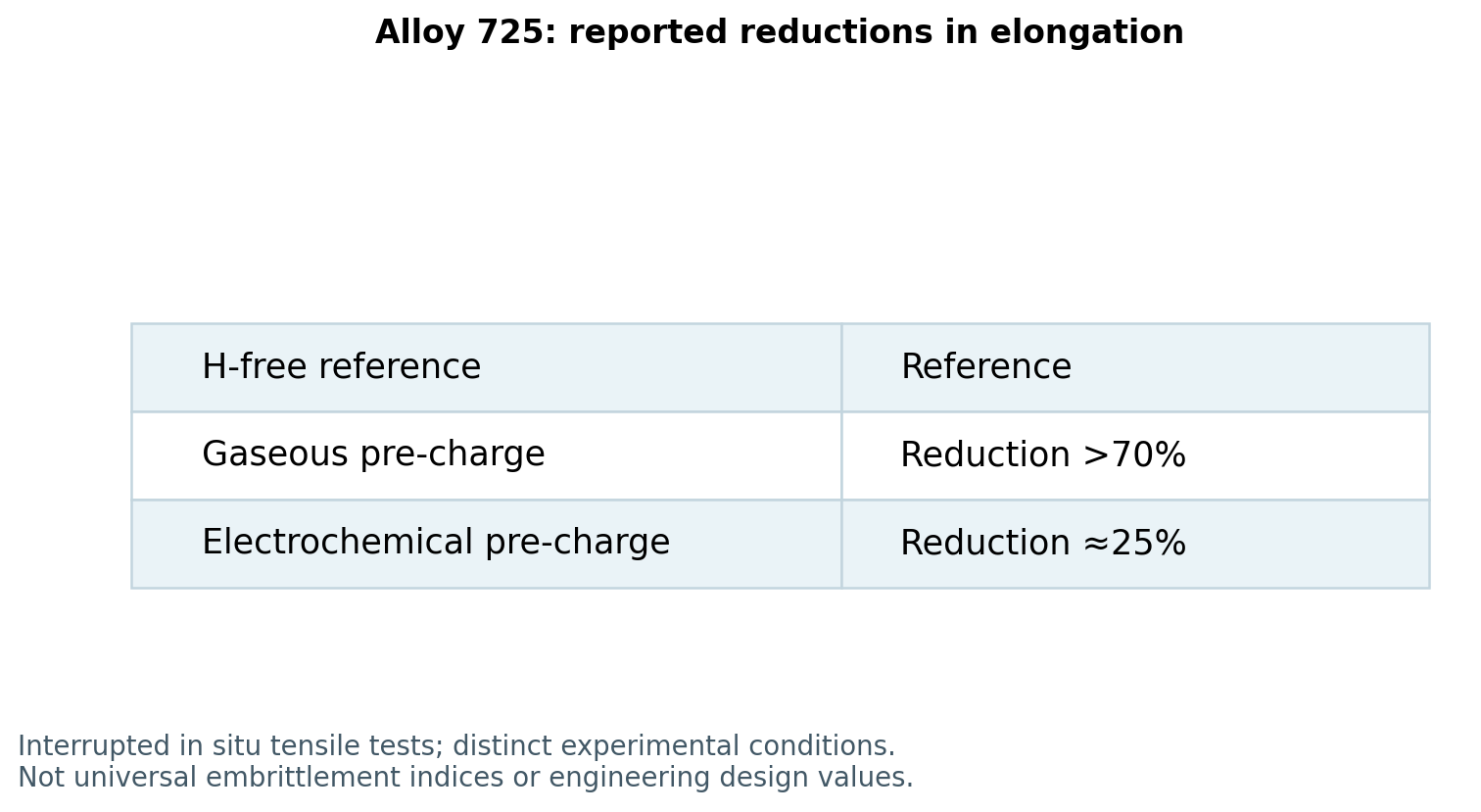
The researchers reported a greater than 70% reduction in elongation to failure for the gaseous specimen and approximately 25% for the electrochemically treated specimen relative to the hydrogen-free reference under their experimental protocol. Those percentages should not be extrapolated into component acceptance limits or general material properties.
The authors also explained a scientific limitation: it was not possible to completely separate the effects of the charging method itself from the different hydrogen distributions created by those methods. Their evidence supports caution when assuming apparently comparable pre-charging conditions produce equivalent damage.
The paper was written by Mengying Liu, Patrick Schools, Lai Jiang, Jacob Jackson and Michael J. Demkowicz and published on October 12, 2026. Electrochemical pre-charging lasted about 50 h at 4.98 mA/cm². Gaseous charging used 138 MPa and 300 °C for approximately seven days, followed by cooling. These are reported research procedures, not operating instructions or equivalent service exposures.
The detailed comparison uses one hydrogen-free reference and one specimen per pre-charging condition; the surface-cracking pattern was corroborated in three specimens per method. Elongation was represented by displacement divided by gauge length in interrupted in-situ tensile tests at an average strain rate of 4 × 10⁻⁵ s⁻¹. Stress drops in the plot correspond to pauses for imaging. These results are not a statistical distribution of industrial component properties.
Local hydrogen profiles were calculated from bulk measurements using a finite-slab diffusion model with surface ingress and outgassing during testing. They are not point-by-point measurements of local concentration. The authors could not fully disentangle charging-method effects from the resulting spatial distribution. Surface slip observations alone do not demonstrate the HELP mechanism.
| Observation | Study condition | What cannot be concluded |
|---|---|---|
| Surface cracking | More secondary cracks after electrochemical charging | That this method is always more damaging. |
| Elongation | Reduction >70% gaseous; about 25% electrochemical | An equal loss of strength or service life. |
| CT | Normalized distributions peak at different depths | That raw defect counts rank risk. |
| Hydrogen profiles | Inferred through diffusion modeling | That local concentration was measured directly. |
A simple diffusion exercise
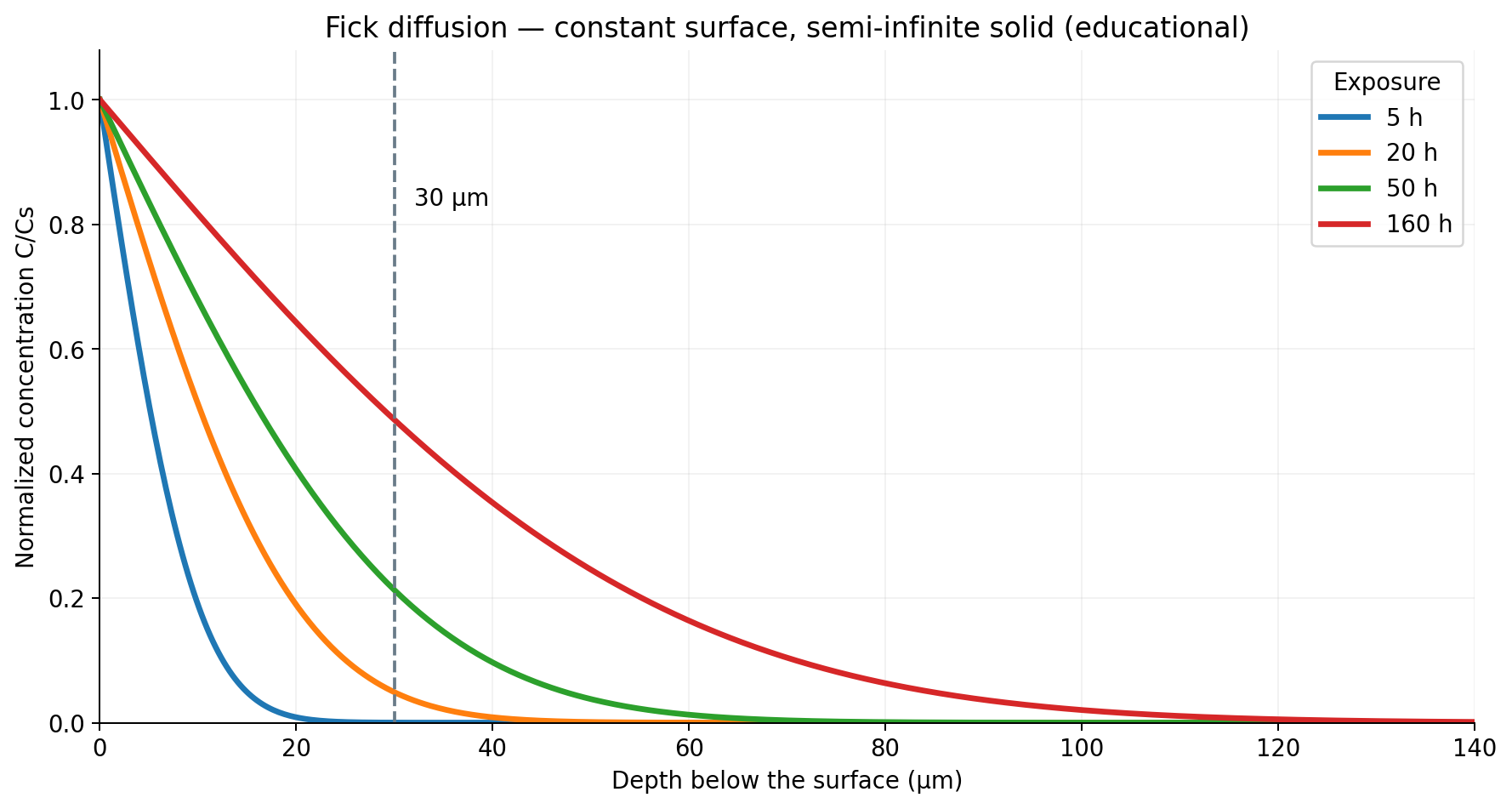
For an idealized semi-infinite solid, initially free of hydrogen, and fixed surface concentration Cs, Fick's solution can be written as:
C(x,t)/Cs = erfc[x / (2√(D·t))]
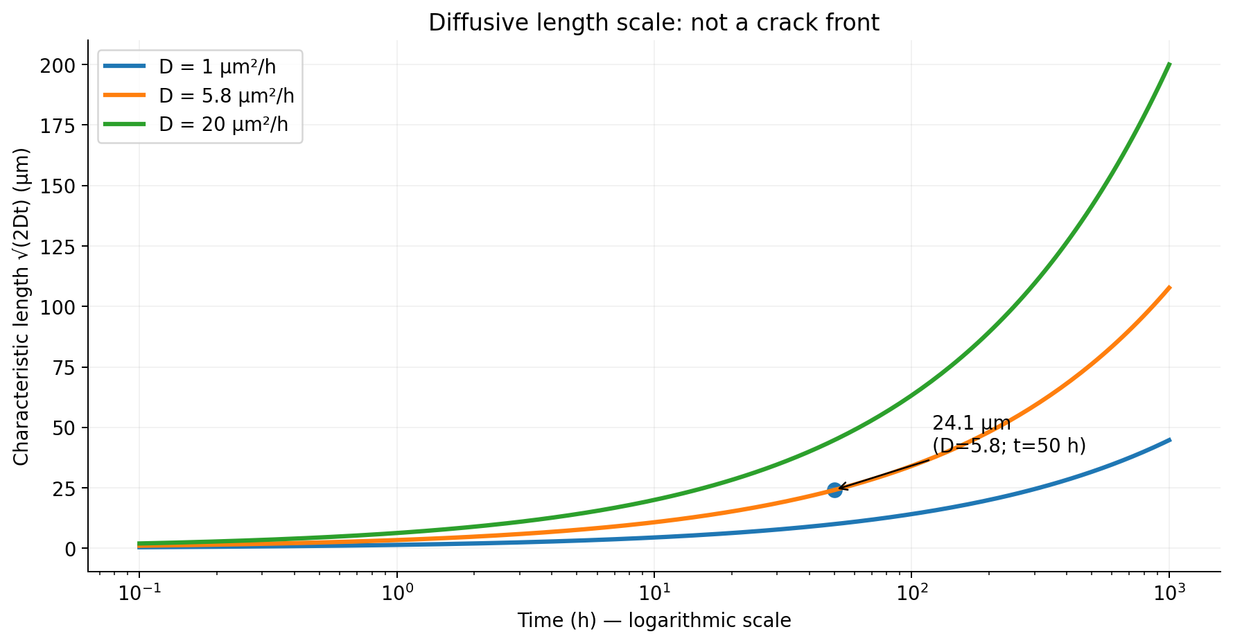
Here, x is depth, t is exposure time, and D is a constant diffusion coefficient. Define a useful diffusion length scale as L = √(2Dt). This is not a crack front or failure threshold.
Using D = 5.8 µm²/h as a didactic value referenced by the paper and t = 50 h gives:
L = √(2 × 5.8 × 50) = 24.08 µm
At a depth of 30 µm, the analytical concentration ratio is C/Cs ≈ 0.213. A characteristic diffusion length of 30 µm requires about 77.6 h under the same ideal assumptions. This calculation neither replicates the paper's finite specimens and charging conditions nor predicts cracks, embrittlement severity or component lifetime.
A small interactive lab in the kit allows readers to vary diffusivity, time and depth in English, Portuguese and Spanish.
Hydrogen diffusion — educational laboratory
Explore how exposure time and diffusivity change an idealized hydrogen profile. Not a crack or lifetime predictor.
Mathematical results
- Scale √(2Dt)
- 24.08 µm
- C/Cs at depth
- 21.29%
- Time for √(2Dt)=x
- 77.59 h
Current profile values
| Depth (µm) | C/Cs |
|---|---|
| 0 | 1.000000 |
| 10 | 0.677975 |
| 20 | 0.406282 |
| 30 | 0.212881 |
| 50 | 0.037881 |
| 100 | 0.000033 |
| 150 | 0.000000 |
Idealized one-dimensional semi-infinite diffusion with fixed surface concentration and constant D. No trapping, stresses, loading or cracking. Not for engineering design.
Initial condition: C(x,0)=0 for x>0; C(0,t)=Cs for t>0; C(∞,t)=0. D and Cs are constant. No desorption, trapping, stresses, thermal gradients, loading, cracks or lifetime are modeled. √(2Dt) is not a physical front.
The value 5.8 µm²/h is an educational reference associated with the study conditions, not a universal property of alloy 725. The relation t=x²/(2D) only inverts the scale; it is not time to reach a concentration or initiate failure.
Applications in energy and mechanical integrity
Hydrogen-affected cracking matters to the design and evaluation of gas pipelines, welded joints, high-strength fasteners, pressure vessels and selected offshore components. The US Department of Energy identifies hydrogen compatibility of steels and welds as an important challenge for pipelines. NIST research has also assessed fracture properties of pipeline welds in hydrogen.
Real-world root-cause analysis should record the material grade and condition, joining and coating history, hydrogen sources, service stress, time, environmental conditions and independent evidence from microscopy or mechanical testing. ASTM G142 covers mechanical testing in hydrogen-containing gaseous environments; ASTM F519 has a more specific scope relating to steel plating/coating processes and service exposure. These standards do not guarantee immunity to hydrogen damage.
The public summaries of ASTM G142-98(2022) and F519-23 were checked; no unconsulted paywalled clauses are asserted. F519-23 assesses coating/plating processes and chemical environments on steels, rather than ranking different steels. G142 results may not correlate with actual service.
Are embrittlement, HIC and high-temperature hydrogen attack the same?
HE broadly describes hydrogen-assisted loss of properties and damage. In steel integrity work involving aqueous H₂S environments, HIC commonly refers to hydrogen-induced cracking associated with traps and inclusions; terminology needs context. HTHA is high-temperature hydrogen attack, involving reactions such as methane formation, decarburization and internal damage in susceptible steels. It is distinct from the embrittlement examined here and cannot be diagnosed merely from the presence of H₂.
Engineering lessons and prevention
Select qualified materials for actual service conditions, control manufacturing and coating processes, review applied/residual stresses, test under appropriate environments and preserve inspection and maintenance records. Preventive strategies vary across alloy systems and mechanisms.
The lesson of the new alloy 725 paper is concise: hydrogen concentration, where it accumulates and how it entered are interconnected engineering variables. Understanding them supports sounder failure investigation and safer infrastructure design.
A short glossary
| Term | Meaning |
|---|---|
| Strength | Stress sustained under specified test conditions. |
| Ductility | Ability to undergo plastic deformation before rupture. |
| Fracture toughness | Resistance to crack extension under specified conditions. |
| Hydrogen trap | Microstructural site affecting hydrogen mobility and occupancy. |
| DIC / EBSD | Image-based displacement/strain measurement / crystallographic orientation. |
Connections with other damage mechanisms
Our discussion of metal fatigue distinguishes cyclic damage from hydrogen diffusion. Metal creep concerns time-dependent deformation, especially at elevated temperatures; it is a separate mechanism. Mechanical vibration and resonance can amplify alternating stresses and therefore belong in the loading assessment.
Laboratory and study resources
Technical and visual-documentation review: October 17, 2026. The lab only represents an idealized mathematical solution: one surface, an initially hydrogen-free semi-infinite medium, constant Cs and D, no trapping, stress effects or desorption. It does not reproduce tomography or predict cracks, safety or service life.
Open the standalone laboratory (PT/EN/ES) →
Exercise CSV: D = 5.8 µm²/h and t = 50 h →
Download the revised kit with articles, figures and credits →
Primary sources and public scopes
Liu, Schools, Jiang, Jackson & Demkowicz (2026) — Journal of Materials Research →
Martin et al. (2019) — NIST / HELP →
NIST — Pipeline welds and hydrogen →
CSB — Tesoro report, HTHA (§4.1) →
Frequently asked questions
Is hydrogen embrittlement the same as corrosion?
No. Corrosion reactions can supply hydrogen, but visible surface corrosion and hydrogen-assisted damage are different concepts.
Does it only affect steel?
No. The 2026 study involved a nickel alloy; responses differ greatly among materials.
Can the diffusion lab predict rupture?
No. It visualizes a deliberately simplified mathematical profile, not a fracture mechanics model.
What do HEDE and HELP mean?
They are proposed mechanisms involving decreased local cohesion and hydrogen-enhanced localized plasticity, respectively.
Why compare gaseous and electrochemical charging?
Because different methods can produce different hydrogen gradients and crack populations even when bulk hydrogen content seems comparable.
References
- Liu, Schools, Jiang, Jackson & Demkowicz (2026) — Journal of Materials ResearchSpringer Nature / Journal of Materials Research
- Martin et al. (2019) — NIST / HELPNIST
- DOE — Hydrogen pipelinesU.S. Department of Energy
- NIST — Pipeline welds and hydrogenNIST
- ASTM G142 — public scopeASTM International
- ASTM F519-23 — public scopeASTM International
- CSB — Tesoro report, HTHA (§4.1)U.S. Chemical Safety Board
- NIST — Materials Testing in Extreme EnvironmentsNIST