
AEP announces a planned 702 MW Bloom Energy fuel-cell project for Google. Learn the SOFC electrochemistry, thermal balance, efficiency and emissions caveats.
702 MW in the announcement: what AEP plans to build
On October 14, 2026, American Electric Power announced a planned 702 MW Bloom Energy fuel-cell project near Cheyenne, Wyoming, to serve Google’s demand. The announced investment is approximately $4 billion. This is planned generating capacity: the announcement does not establish that commercial generation has begun or that this capacity is already available to the customer.
The announced project company is Cheyenne Fuel Cell LLC, approximately 92% owned by AEP, with nearly 8% held by funds advised by Basalt. Google’s role is supported by a 20-year power purchase agreement, or PPA. Contracting to purchase electricity does not mean purchasing ownership of the power plant, and the announcement does not disclose a contractual electricity price.
Construction is expected to begin in 2026, with full operation anticipated by the end of 2028. The announcement raises an engineering question: how can electricity be generated without a flame as the main conversion step? The answer involves electrochemistry alongside fuel supply, high temperatures, materials, auxiliary equipment, and careful management of emissions throughout the system.
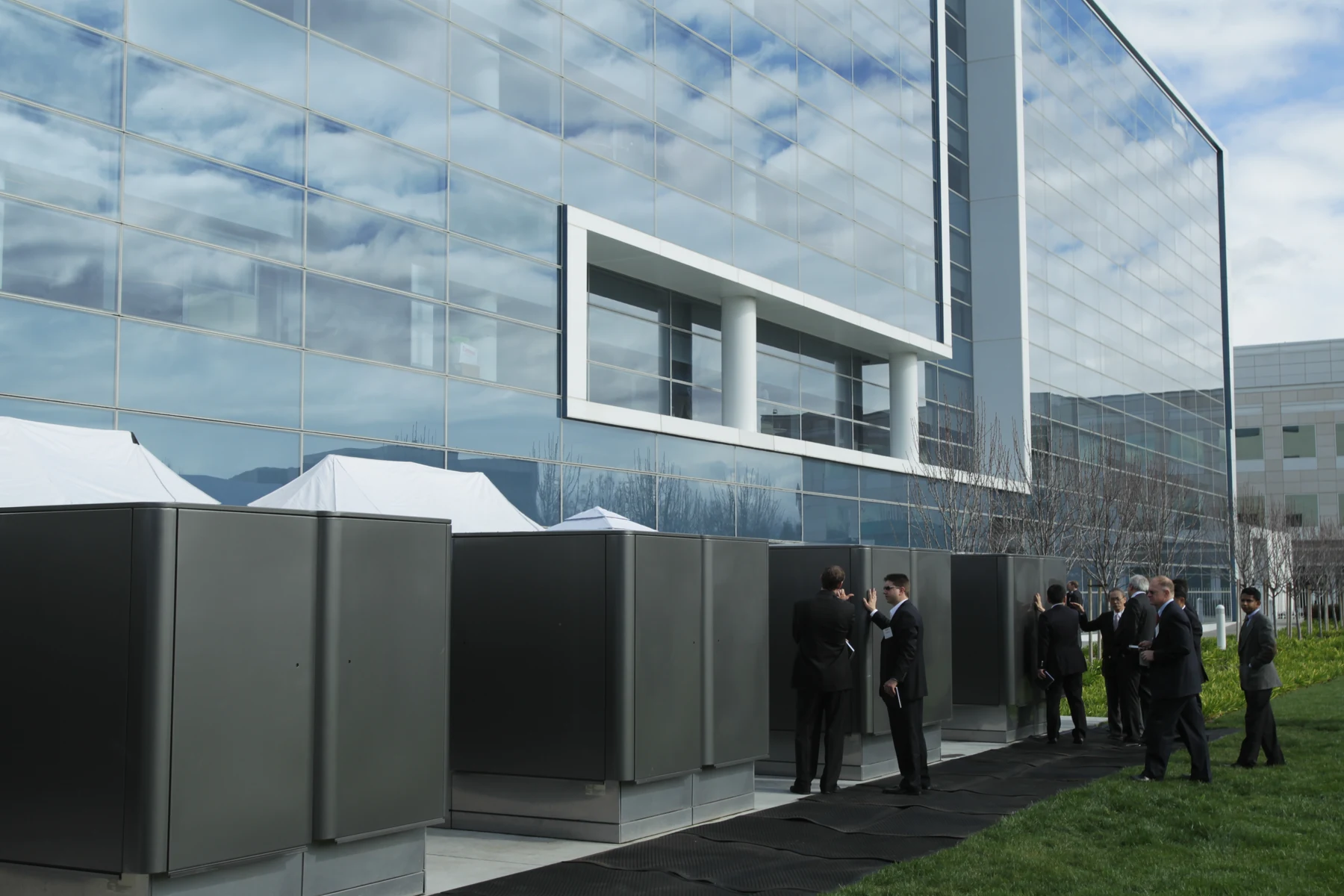
Project facts and assumptions in this study
Three different kinds of information must remain distinct. AEP’s release describes the planned development and schedule. DOE and NETL explain the technology and its engineering principles. The calculations below use teaching assumptions selected for this article. An efficiency chosen for a worked example does not become a contractual specification or a measured result for Cheyenne.
The information does not establish a 60% net electrical efficiency, guaranteed annual output, or a particular carbon capture rate for this development. Nor should 702 MW be treated as the measured demand of one specific data center. Generating capacity, instantaneous electrical demand, and energy accumulated over time are different quantities with different measurement boundaries.
Bloom has published discussions of direct-current power architectures for data centers. These provide industrial context, but they do not document Cheyenne’s electrical design. Without project-specific documentation, it would be inappropriate to assign a distribution voltage, redundancy arrangement, or direct connection between modules and servers. Thermal specifications require the same discipline about what has actually been disclosed.
Bloom Energy — The New Rules of AI Power →
| Item | Announced information | Boundary |
|---|---|---|
| Capacity | 702 MW planned | Not measured operating output |
| Investment | Approximately $4 billion | Not the PPA electricity price |
| Agreement | 20-year Google PPA | Not plant ownership |
| Schedule | Construction 2026; full operation late 2028 | Announced expectations |
| Carbon | Capture integration plans | No verified capture performance |
From a ceramic cell to a power plant
SOFC stands for solid oxide fuel cell. The device contains porous electrodes and a solid ceramic electrolyte, operating at high temperature. Its arrangement allows chemical species to react at specific locations while an external circuit receives electrical current. A turbine is not required for this fundamental conversion, although an entire installation still needs extensive supporting equipment.
An individual cell is different from a complete installation. Cells are combined into stacks, stacks and associated equipment form modules, and modules are integrated into a generating facility. Each level introduces connections, losses, constraints, and control requirements. The performance of one isolated element therefore does not automatically describe the net efficiency of the complete power plant.
An SOFC is also different from a conventional battery carrying its usable reactant inventory internally. A fuel cell requires a continuing supply of fuel and oxidant. Questions about operating duration therefore depend on fuel delivery, module availability, and operating conditions as well as electrochemistry. The word “cell” alone does not tell us how much energy is stored or available.
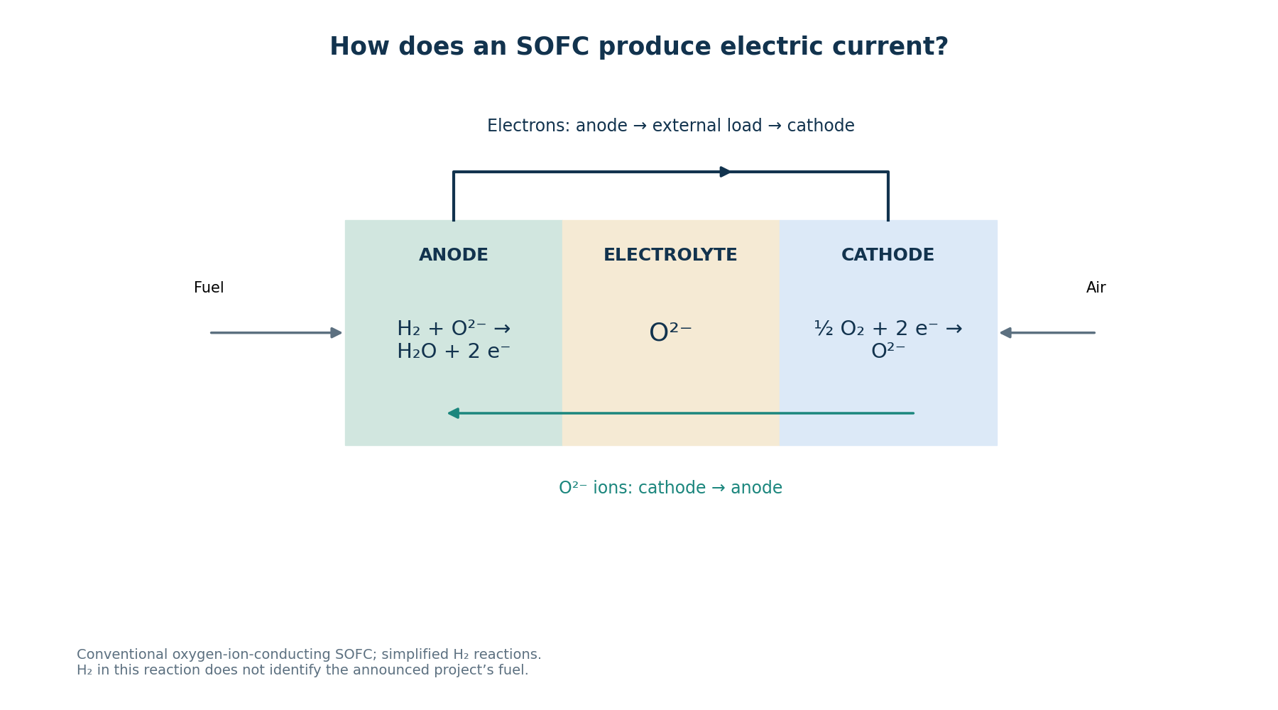
The paths taken by ions and electrons
In a conventional oxygen-ion-conducting SOFC, oxygen receives electrons at the cathode: ½ O₂ + 2 e⁻ → O²⁻. The oxygen ions travel through the ceramic electrolyte toward the anode. Ionic conduction depends on the material and thermal conditions. The electrolyte is not a metallic wire carrying the electrons that power the external electrical circuit.
Using hydrogen as a teaching reaction, the anode reaction is H₂ + O²⁻ → H₂O + 2 e⁻. Released electrons leave the anode through the external circuit, supply the load, and return to the cathode. Separate ionic and electronic paths enable electrical work to be extracted. This simplified reaction teaches the mechanism rather than describing every commercial reaction.
Writing hydrogen in this equation does not mean Cheyenne will run exclusively on H₂. The announcement refers to natural gas, whose processing involves reforming and carbon-containing species. A stack produces direct current, and practical use may require power electronics and DC-to-AC conversion. The voltages of a cell, a module, and the electrical interconnection are separate specifications.
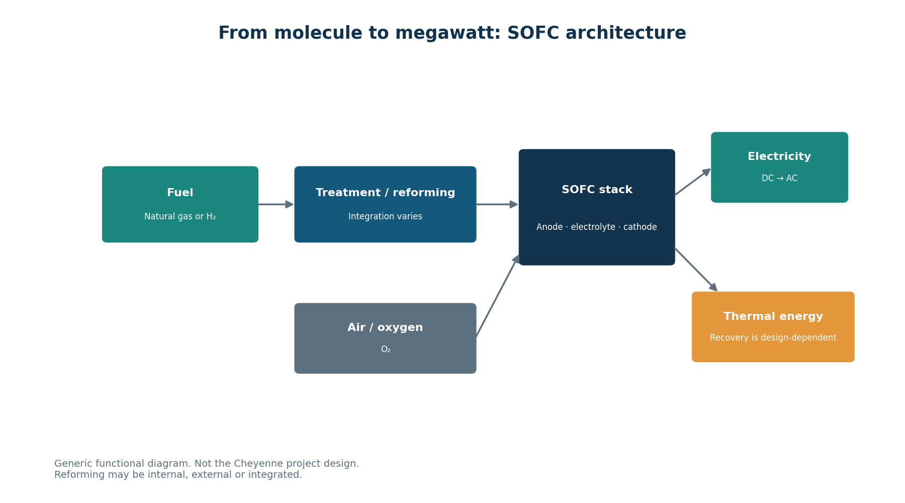
The engineering that supports the reaction
The balance of plant includes the systems that enable a stack to operate: fuel preparation, air supply, heat exchangers, piping, valves, instrumentation, and electrical converters. Reforming may be external, internal, or integrated, depending on the technology. A functional diagram must not be interpreted as a universal requirement for a separate external reformer in every commercial SOFC.
Blowers consume electricity, flow restrictions create pressure losses, and heat exchangers require finite temperature differences. Preheating streams can improve energy integration but demands surface area, suitable materials, and control. Analysis must track mass and energy from inlet to outlet, including auxiliaries. Omitting these loads would overstate the electrical performance available at the actual delivery boundary.
Operation still requires attention to fuel leaks, hot surfaces, insulation, ventilation, and responses to abnormal conditions. Monitoring temperature and gas composition helps protect the installation, but specific requirements depend on its design. These are engineering disciplines relevant to the technology, rather than claims about Cheyenne’s interlocks or a substitute for its detailed safety and operating documentation.
Heat, irreversibility, and maximum work
Electrochemical conversion does not bypass thermodynamics. The relation ΔG = ΔH − TΔS distinguishes the Gibbs free-energy change from the reaction enthalpy change. At constant temperature and pressure, the maximum reversible electrical work delivered is −ΔG. The sign matters: ΔG is not electrical power, and reaction energy must not be confused with energy transferred per second.
A real cell has activation, ohmic, and mass-transport losses, alongside the requirements of gas processing. Energy remains in products and thermal streams, with its distribution depending on operating conditions. A thermodynamic identity cannot by itself tell us how much useful heat a heat exchanger will recover from an installation whose temperature levels and detailed configuration have not been specified.
Even high electrical efficiency leaves a thermal problem to solve. Heat must move without imposing excessive ceramic temperature gradients, damaging seals, or upsetting fuel processing. Recovery requires a use compatible with the available temperature. Accounting for energy and evaluating its ability to perform a useful task are related analyses, but one cannot replace the other in system design.
Efficiency depends on the measurement boundary
DOE describes electrical efficiency around 60% for SOFCs and total energy utilization above 85% in certain cogeneration applications. These are technology references. The description does not state every LHV/HHV, DC/AC, and gross/net criterion needed to define our comparison for that 60% figure. We should not fill those gaps by assigning an undocumented performance boundary to Cheyenne.
Lower heating value, LHV, and higher heating value, HHV, use different reference treatments for water in the products. With the same fuel input and electrical output, an LHV-based efficiency is numerically higher. The equipment has not started generating more electricity; the denominator has changed. Fair comparison therefore requires the heating-value basis to be stated explicitly.
Gross stack electricity must also be distinguished from net power delivered after auxiliary loads and conversion. The following exercises explicitly assume net AC electrical efficiency on an LHV basis. That teaching assumption makes the arithmetic internally consistent, but it is neither certification nor a test result or commercial commitment by AEP, Bloom, or Google for this project.
| Boundary | What must be stated |
|---|---|
| Fuel input | LHV or HHV |
| Electrical output | DC or AC |
| Auxiliaries | Gross or net power |
| Operation | Load and assessment conditions |
| This exercise | Assumed 60% net AC efficiency on an LHV basis |
702 MW and a hypothetical energy balance
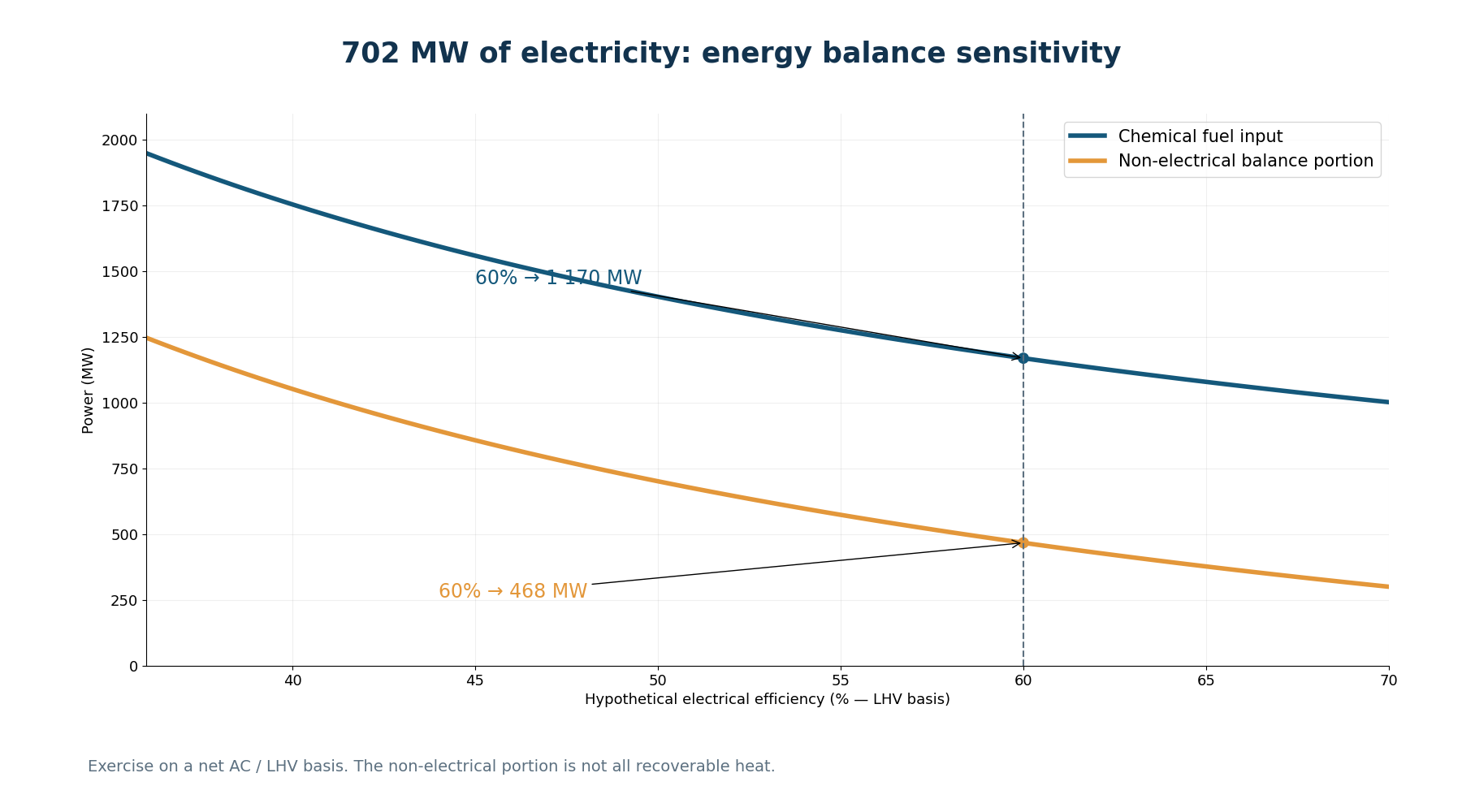
Take Pₑ = 702 MW and an assumed efficiency ηₑ = 0.60. From ηₑ = Pₑ/Pfuel, the chemical input would be 702/0.60 = 1,170 MW_LHV. The portion not converted into electrical output would be 1,170 − 702 = 468 MW. The capacity comes from the announcement; the efficiency and the resulting operating scenario are our teaching assumptions.
The 468 MW figure is not measured exhaust heat and cannot be advertised as fully recoverable heat. It is the non-electrical remainder of this simplified balance. Useful recovery requires temperatures, streams, losses, enthalpies, and the receiving thermal demand to be characterized. This distinction prevents an energy conservation calculation from becoming an unsupported promise about cogeneration performance.
If we select a purely illustrative recovery fraction of 40% of that remainder, the result is 0.40 × 468 = 187.2 MW. This is a hypothetical subset of the 468 MW, not an additional energy stream to add to the input. At an assumed 50% electrical efficiency, 702 MW would require 1,404 MW_LHV and leave a 702 MW non-electrical remainder.
| Hypothetical scenario | Input MW_LHV | Electrical output MW | Non-electrical remainder MW |
|---|---|---|---|
| η = 60% | 1,170 | 702 | 468 |
| η = 50% | 1,404 | 702 | 702 |
Installed capacity is not annual energy
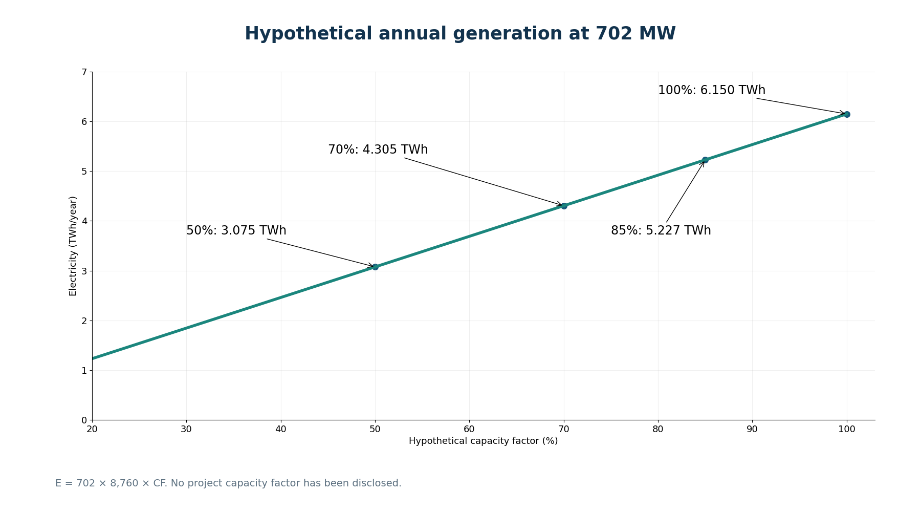
MW measures power; MWh and TWh measure energy. In a conventional 8,760-hour year, maintaining 702 MW throughout every hour would produce 6,149,520 MWh, or 6.14952 TWh. This multiplication describes an arithmetic result under stated conditions. It is not an official generation forecast or evidence that the equipment will run continuously at that output.
Capacity factor compares energy actually generated over a period with the energy from continuous operation at rated capacity. Choosing an illustrative 85% gives E = 702 × 8,760 × 0.85 = 5,227,092 MWh, or 5.227092 TWh. That percentage was not taken from an availability guarantee, Google’s agreement, or a disclosed operating forecast for this development.
Outages, part-load operation, and dispatch constraints can change annual generation. Capacity factor is not electrical efficiency: one indicator relates output and time, while the other relates electrical output to fuel input. A facility can have good efficiency while running and still deliver less annual energy if it spends fewer hours in service or operates below rated capacity.
What approximately $5,698 per kW tells us
Dividing the approximate announced investment by rated capacity gives a sense of scale: $4,000,000,000 / 702,000 kW ≈ $5,698/kW. The denominator must be in kW to obtain that unit. Because the investment itself is approximate, reporting cents or excessive significant figures would suggest a level of precision absent from the original announcement.
This ratio is not the PPA electricity price, is not measured in dollars per kWh, and does not separate stack costs from other systems. Construction, infrastructure, integration, and additional elements can contribute to a development. Without an itemized budget, the full amount cannot be assigned to electrochemical equipment or compared directly with a supplier’s quotation for modules.
Economic feasibility would require fuel, operations, maintenance, replacements, financing, availability, revenues, and environmental constraints to be assessed. Contract duration and component service life are different matters as well. Our calculation interprets two public numbers using the correct units; it does not invent a tariff, payback period, or levelized cost of electricity for the project.
SOFC and Brayton: different conversion paths
In the gas-turbine model associated with the Brayton cycle, compression is followed by heat addition and expansion. Part of the turbine work drives the compressor; the remaining work can drive a generator. An SOFC delivers electricity electrochemically at its fundamental conversion stage. The conversion path changes, but auxiliary consumption and thermal management remain essential to the complete system.
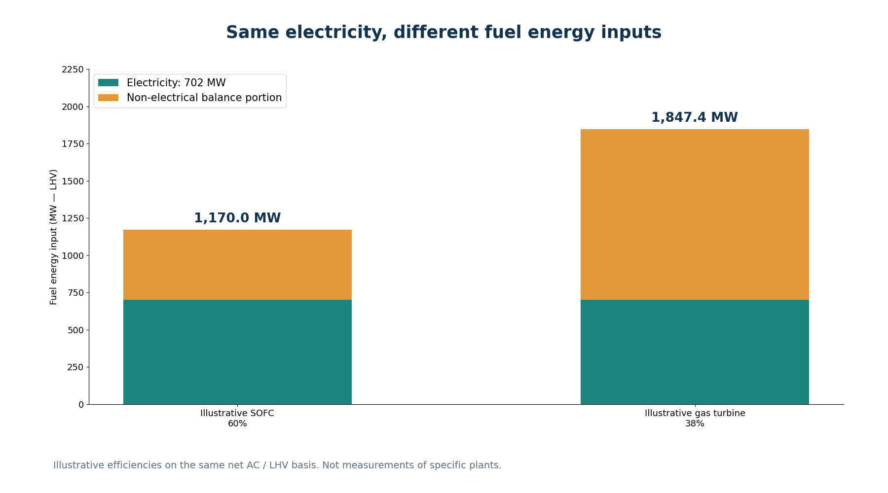
For illustration only, keep a common boundary of net AC output and LHV fuel input. A hypothetical 60% SOFC would need 1,170 MW_LHV to deliver 702 MW; a hypothetical 38% turbine would require 1,847.368 MW_LHV. The input difference would be 677.368 MW_LHV. Neither efficiency is a measurement of the announced project or a specification for a particular turbine.
The arithmetic does not prove universal superiority: startup, ramping, maintenance, investment, availability, and integration can change the preferred option. SOFC–gas-turbine hybrids are also being researched, combining the two conversion paths. NETL discusses such arrangements. Comparing technologies requires defining the required service and system boundary, rather than treating one chosen efficiency percentage as a complete engineering verdict.
NETL — SOFC and Gas Turbine Hybrids →
| Assumption, common boundary | Net AC/LHV efficiency | Input for 702 MW |
|---|---|---|
| Teaching SOFC | 60% | 1,170 MW_LHV |
| Teaching turbine | 38% | 1,847.368 MW_LHV |
| Arithmetic difference | Not a commercial comparison | 677.368 MW_LHV |
Without a flame does not mean zero emissions
Natural gas contains carbon. Processing and using it in a fuel cell can produce CO₂ even when the principal electrochemical step does not rely on conventional combustion. “Without combustion” must therefore be read within that specific physical boundary. It does not establish the absence of greenhouse gases from the complete installation or from its fuel supply chain.
AEP’s announcement mentions plans to integrate carbon capture. A plan is not commissioning or verified performance. The announcement does not establish a capture rate, associated energy demand, or measured residual emissions. An ambition for near-zero emissions depends on future conditions and must not be presented as an outcome already demonstrated by an operating facility.
A consistent environmental assessment distinguishes on-site emissions, the fuel supply chain, and life-cycle effects. Upstream leakage, processing, and energy used by supporting systems may matter. Comparisons with other technologies require equivalent boundaries and suitable data. Potential reductions can be discussed without assigning emission factors or quantified benefits to this project that have not been established.
Ceramics, thermal cycling, and reliability
High temperature supports ionic conduction but creates materials challenges. Ceramics, metals, and seals respond differently to thermal expansion. Gradients and cycling must be managed to limit stresses, cracking, and degradation. Initial efficiency is therefore insufficient: engineers also need to understand how performance and integrity evolve over operating time and across starts, stops, and changing conditions.
Fuel quality and contaminants matter as well. Inadequate preparation can affect electrodes, reforming, and service life; specific limits depend on the manufacturer and feed. Warmup time, load-following capability, and maintenance strategy influence suitability for a particular duty. A data center needs electrical continuity, which must be demonstrated through more than the sum of module nameplate capacities.
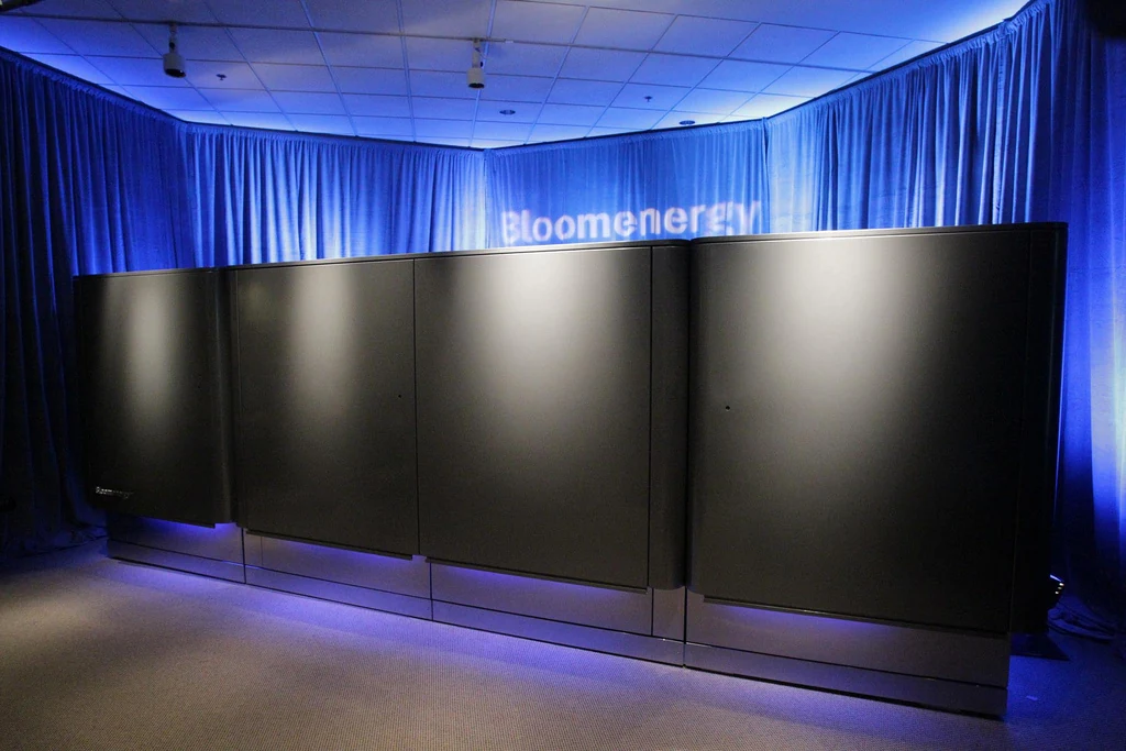
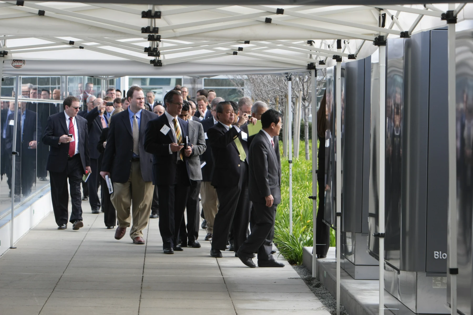
The technology may be less suitable when the required operating profile conflicts with its limitations or when infrastructure and costs undermine feasibility. Adding capture introduces equipment and energy balances that need assessment. The archival photographs in this article show real systems, but they are not an inspection, safety record, or demonstration of performance for the planned Cheyenne development.
A laboratory for checking the arithmetic
The supporting materials let readers repeat the examples with different capacity, efficiency, capacity factor, and hypothetical recovery fractions. The HTML can be downloaded and opened separately as a study resource. This article retains its static calculations and figures so the reasoning remains accessible without depending on an embedded simulator or on successful execution of interactive code.
When changing a parameter, check its unit before interpreting the result. The recovered fraction belongs within the non-electrical remainder; capacity factor affects annual energy; efficiency changes the fuel input needed for a given electrical output. Changing all three at once without recording the assumptions makes it harder to identify which change caused each numerical result.
None of the materials calculates actual emissions, sizes protective devices, or guarantees contracted performance. The examples support consistency checks, boundary comparisons, and sensitivity discussions. Recording assumptions is part of technical quality: a reproducible calculation with a clear scope teaches more than an impressive number presented without its origin, units, or conditions of validity.
Download the HTML laboratory (PT/EN/ES) →
Electricity without a flame still needs thermal engineering
The announcement highlights a different energy conversion route and raises relevant questions about power infrastructure for computing. Its technical value does not depend on promising an absence of losses or emissions. The useful lesson is to follow reactants, ions, electrons, and thermal streams while separating the announced development, established technology principles, and academic worked examples.
An SOFC can generate electricity without a flame at the main conversion stage while still demanding sophisticated thermal engineering. Our articles on gas turbines, heat exchanger sizing, and liquid cooling for data centers explore complementary parts of that chain. The decisive question remains practical: which complete system can deliver the required service with performance that can actually be demonstrated?
Gas turbines and on-site power for AI data centers →
Frequently asked questions
What does SOFC stand for?
SOFC stands for solid oxide fuel cell: a high-temperature electrochemical device with a solid ceramic electrolyte. It receives fuel and oxidant to generate electricity.
Can SOFCs run on natural gas?
They can, depending on the system. Natural gas requires processing and reforming, which may be external, internal, or integrated. Cheyenne’s announcement refers to natural gas; the H₂ reaction in this article is a teaching example.
Is an SOFC a battery?
It is different from a conventional battery. It requires continuing fuel and oxidant supplies rather than relying solely on an internal reactant inventory. Availability also depends on supply infrastructure and auxiliary systems.
Does combustion-free mean zero CO₂?
No. Carbon-containing fuel can produce CO₂ during processing and use. The absence of a flame in the electrochemical conversion step does not demonstrate zero emissions for the installation or its life cycle.
What is the efficiency of an SOFC?
It depends on the technology and boundary, including LHV/HHV, DC/AC, and gross/net output. DOE cites around 60% as a technology reference. Our separate exercise assumes 60% net AC on an LHV basis, not a Cheyenne performance figure.
How does an SOFC differ from the Brayton cycle?
An SOFC converts chemical energy electrochemically. A gas turbine uses compression, heat addition, and expansion to provide mechanical work. Hybrid systems combine SOFCs and turbines; any comparison requires equivalent system boundaries.
Are the 702 MW already operating?
That is not what the announcement establishes. On October 14, 2026, AEP presented the project, with construction expected in 2026 and full operation anticipated by the end of 2028. Planned capacity is not measured generation.
Did Google buy the power plant?
The announcement describes a 20-year PPA to purchase electricity. The project company is Cheyenne Fuel Cell LLC, approximately 92% AEP and nearly 8% funds advised by Basalt. An electricity agreement must not be confused with ownership of the plant.
Has carbon capture already been installed?
The release mentions plans to integrate capture. It does not demonstrate commissioning, capture rate, or verified residual emissions. A future environmental ambition must not be presented as proven operating performance.
How is annual energy calculated for 702 MW?
For a 365-day year, use E = P × 8,760 × capacity factor. At 100%, the result is 6.14952 TWh; at an assumed 85%, it is 5.227092 TWh. These are arithmetic exercises, not official AEP forecasts.
References
- AEP — 702 MW announcementAEP
- Reuters — AEP fuel-cell project for GoogleReuters
- DOE — Types of Fuel CellsU.S. Department of Energy
- NETL — SOFC Operating PrincipleNETL
- DOE — Fuel Cell SystemsU.S. Department of Energy
- NETL — Fuel Cell Handbook, seventh editionNETL
- NETL — SOFC Demonstration SystemNETL
- NETL — SOFC and Gas Turbine HybridsNETL
- NASA Glenn — Brayton CycleNASA
- Bloom Energy — The New Rules of AI PowerBloom Energy
- Wikimedia Commons — Bloom Energy Servers at eBay HQ.jpgBloom Energy / Jakub Mosur
- Wikimedia Commons — Bloom Energy Servers.jpgBloom Energy / Jakub Mosur
- Wikimedia Commons — Touring the Bloom Energy Servers.jpgBloom Energy / Jakub Mosur
- Creative Commons Attribution 2.0Creative Commons