
How does liquid cooling for AI chips work? Explore cold plates, CDUs, flow rates and heat exchangers, with a worked 100 kW example.
AI computes in silicon — and heat needs a way out
In a data center, artificial intelligence relies on calculations taking place in microscopic semiconductors and on a thermal system that removes the heat they produce. Cold plates, pumps, manifolds and heat exchangers form part of this physical infrastructure. A project announced in Mumbai on October 12, 2026 provides a starting point for following that path.
Direct-to-chip liquid cooling removes heat from electronic components through cold plates in thermal contact with them and through liquid circulating internally in a dedicated circuit. The system carries energy to another circuit, the environment or a compatible thermal use. We will follow that route and solve a hypothetical 100 kW example, independent of the Indian project.
What was announced in Mumbai — and what 30 MW does not measure
According to a Vertiv announcement reproduced by Express Computer and Webnewswire on October 12, 2026, the company deployed a high-density direct-to-chip solution with CapitaLand India Trust at CLDC Mumbai 01 in Airoli, Navi Mumbai. The arrangement is described as a Secondary Fluid Network, or SFN, intended to support 30 MW of AI computing capacity for a hyperscale customer.
The description of it as India’s first deployment is a supplier claim. The announcement also describes manufactured and tested skids, contamination control, balancing and Level 4 commissioning. The pages reviewed do not provide an independent audit or measured efficiency, flow rate, chip temperature or water consumption results for this solution.
The announcement date should not be confused with the start of operation. In a release dated July 29, 2026, CapitaLand had already reported handing over its first liquid-cooled data center in Navi Mumbai to a hyperscale customer. Its factsheet presents infrastructure and cooling possibilities; it does not measure the heat load removed by the network announced in October.
The 30 MW figure is announced capacity for AI workloads. It is not a measurement of 30 MW removed by the liquid circuit or the rating of a single CDU. Nor does it allow a design flow rate to be calculated without knowing actual loads, the fraction captured by liquid, temperatures, fluids and architecture. The following exercise uses its own fictional inputs.
Vertiv deployment announcement reproduced by Express Computer →
Vertiv disclosure reproduced by Webnewswire →
CapitaLand India Trust — 1H2026 release; July handover →
| Layer | Information | Interpretation limit |
|---|---|---|
| October 12, 2026 announcement | SFN and 30 MW of announced AI capacity | Not a measurement of heat removed |
| CapitaLand, July 2026 | Handover of a liquid-cooled development | Does not make the October announcement the start of operation |
| Generic engineering | Cold plates, CDU, circuits and heat rejection | Does not identify models installed in this case |
| Andrade Safe exercise | 100 kW, water and a 5 K ΔT | Hypothetical scenario independent of Mumbai |
Why does concentrating computing concentrate heat?
The electrical energy supplied to CPUs, GPUs and other components is converted mainly into heat across the servers. That heat must be removed continuously to keep components within their permitted operating conditions. Concentrating power in small areas creates challenges involving heat flux, uniformity, contact and the distribution of heat removal.
The problem goes beyond the room’s air temperature. Thermal resistances lie between the heat-generating region, the package, the interface and the cooling device. A poorly integrated cold plate can receive liquid under apparently appropriate conditions and still fail to keep the chip temperature within the required limit.
There is no universal rack power ceiling here that makes air cooling unviable in every project. The architecture depends on the equipment and application. Even in direct-to-chip systems, components without cold plates may continue to require airflow. The fraction of heat captured by liquid must be determined for the actual equipment set.
From processor to facility circuit
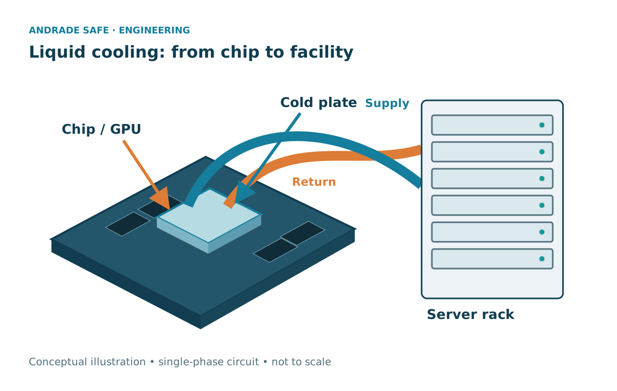
The path starts at the chip, crosses the thermal interface and reaches the cold plate. Its internal channels bring fluid into contact with a heat-transfer surface. The warmed liquid returns through manifolds to the coolant distribution unit, or CDU. Distribution among branches must serve the servers without assuming equal flow rates in every configuration.
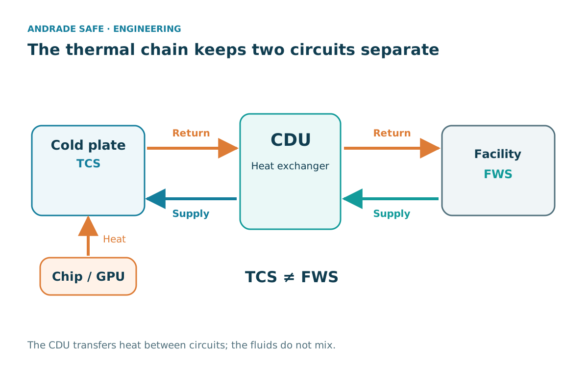
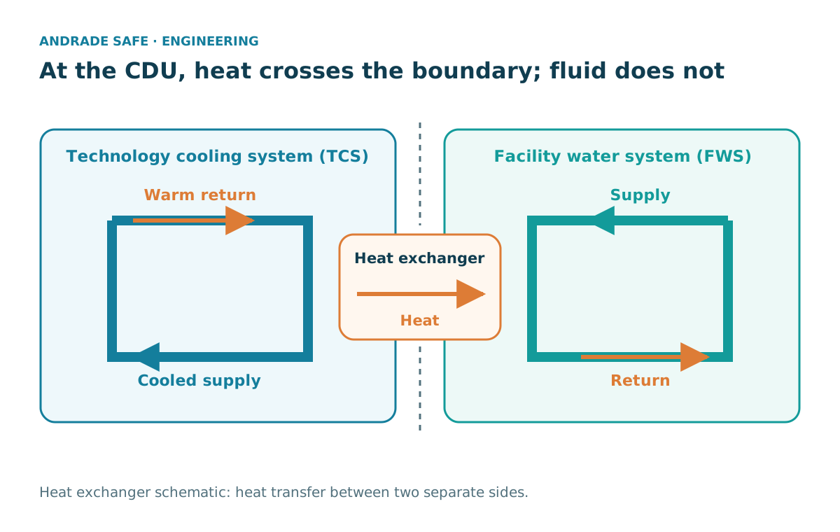
The Technology Cooling System, or TCS, is the technology circuit that serves the equipment and connects it to the CDU. The Facility Water System, or FWS, is the facility circuit. In the illustrated liquid-to-liquid architecture, the heat exchanger transfers heat between these circuits without normal mixing of their fluids. Quality and operating requirements on one side should not automatically be applied to the other.
Hoses, pipes and connectors form part of the route: sealing, materials, contamination and maintenance conditions matter. Depending on its construction, a CDU may combine temperature, flow and pressure control with pumping and heat exchange. Liquid-to-air solutions and other architectures also exist; the name CDU does not define one single arrangement.
The heat still needs to leave the infrastructure. Dry coolers, chillers, cooling towers or heat recovery can participate in rejection or reuse, depending on the design, climate and demand. The liquid circuit does not destroy energy or eliminate this stage. The diagram is generic and does not depict the equipment used at the Mumbai development.
CoolChip CDU — liquid-to-liquid and liquid-to-air architecture →
What can a liquid carry?
For a single-phase fluid at steady state, treating properties as constant, we use Q̇ = ṁ c_p ΔT. Q̇ is the heat-transfer rate in watts, ṁ is mass flow in kg/s, c_p is specific heat capacity in J/(kg·K), and ΔT is the temperature rise in kelvin. A rise of 5 K has the same magnitude as a rise of 5 °C; this does not make absolute temperatures interchangeable.
Volumetric flow is V̇ = ṁ/ρ, with density ρ in kg/m³. Checking units helps: (J/s)/(J/(kg·K) × K) gives kg/s. Dividing by density yields m³/s. The balance estimates how much fluid carries a defined load under these assumptions; it does not calculate the processor’s junction temperature.
The fluid may be treated water or a mixture compatible with the system. Pure water should not be assumed in every direct-to-chip application. Composition and temperature change properties; viscosity also influences flow. Data should come from the relevant documentation. In this exercise, c_p = 4,180 J/(kg·K) and ρ = 997 kg/m³ are fixed approximations adopted for teaching.
Worked example: carrying 100 kW
Consider a hypothetical single-phase cooling segment removing 100 kW, with liquid entering at 30 °C and leaving at 35 °C. We assume steady state, constant properties and no losses to the environment. These temperatures do not represent an ASHRAE class, a GPU temperature or conditions at the Indian project.
After conversion, Q̇ = 100,000 W = 100,000 J/s and ΔT = 35 − 30 = 5 K. Mass flow is ṁ = 100,000/(4,180 × 5) = 4.7847 kg/s, approximately 4.785 kg/s. Applying density, V̇ = 4.7847/997 = 0.0047991 m³/s.
Since an hour contains 3,600 seconds, flow is approximately 17.277 m³/h. To obtain liters per minute, multiply m³/s by 1,000 L/m³ and 60 s/min: about 287.9 L/min. The result demonstrates energy conservation and continuity for the assumed scenario; it does not select a cold plate or a CDU.
| Quantity | Assumption or calculation | Value |
|---|---|---|
| Heat load | Q̇ | 100 kW |
| Segment inlet and outlet | T_in / T_out | 30 °C / 35 °C |
| Temperature rise | ΔT | 5 K |
| Fixed properties | c_p / ρ | 4,180 J/(kg·K) / 997 kg/m³ |
| Mass flow | Q̇/(c_p ΔT) | 4.785 kg/s |
| Volumetric flow | ṁ/ρ | 0.004799 m³/s |
| Hourly flow | V̇ × 3,600 | 17.277 m³/h |
| Flow per minute | V̇ × 60,000 | 287.9 L/min |
A higher ΔT reduces theoretical flow — within limits
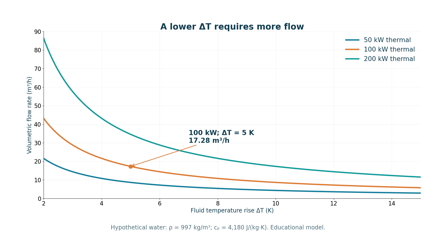
For the same load and properties, calculated flow is inversely proportional to ΔT. Allowing the fluid to warm up more reduces the quantity that needs to circulate in this balance. The table and chart show the relationship for 100 kW, and the chart also covers loads of 50 and 200 kW.
This result does not demonstrate that the chip tolerates any ΔT. Supply temperature, thermal contact, distribution among plates and equipment limits remain decisive. A correct total flow can conceal an underserved branch. Fluid temperature should not be raised without assessing materials, operating conditions and reliability margin.
| ΔT | Mass flow | Volumetric flow |
|---|---|---|
| 3 K | 7.974 kg/s | 28.795 m³/h |
| 5 K | 4.785 kg/s | 17.277 m³/h |
| 8 K | 2.990 kg/s | 10.798 m³/h |
| 10 K | 2.392 kg/s | 8.638 m³/h |
Pumping power also enters the calculation
The fluid encounters losses in pipes, filters, valves, fittings, manifolds, heat exchangers and plate channels. Operating flow depends on the system curve and pump curve. Pressure loss cannot be obtained from the thermal balance alone and may change with flow, fluid and configuration.
For a defined segment, idealized hydraulic power is P_hyd = Δp × V̇. With Δp in Pa and V̇ in m³/s, the result is W. To estimate the electrical portion, P_el = P_hyd/η_overall, where the aggregate efficiency must match the pumping boundary considered. It is not automatically just the pump’s hydraulic efficiency.
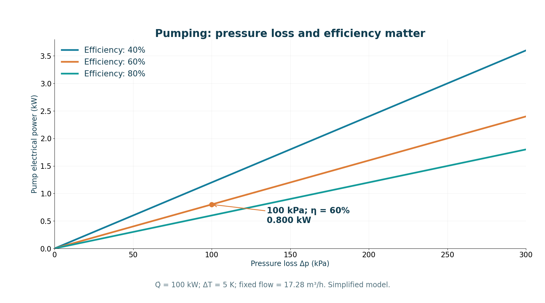
We add a hypothetical total pressure loss of 100 kPa and an overall efficiency of 60% to the example. Thus, P_hyd = 100,000 × 0.0047991 ≈ 479.9 W. Dividing by 0.60 gives P_el ≈ 799.8 W, or 0.800 kW. This is estimated pumping power, not chiller consumption or total cooling consumption.
The chart varies Δp while holding the example’s flow constant and compares three fictional aggregate efficiencies. This teaches the expression’s sensitivity; it is not a pump or network curve. In a real facility, these variables cannot be chosen independently without analyzing operation and component characteristics.
Pressure loss and pipe diameter →
| Item | Assumption | Result |
|---|---|---|
| Total pressure loss considered | 100 kPa = 100,000 Pa | Introduced value, not calculated from the network |
| Aggregate efficiency | η_overall = 0.60 | Pumping assumption |
| Hydraulic power | Δp × V̇ | 479.9 W |
| Estimated electrical portion | P_hyd/η_overall | 799.8 W ≈ 0.800 kW |
The CDU creates a boundary; the exchanger carries heat across it
In a liquid-to-liquid arrangement, the CDU brings two circuits together thermally without mixing their fluids during normal operation. The technology side must serve the equipment; the facility side connects to heat-rejection infrastructure. This separation helps organize fluid control and quality but does not remove the need to consider materials, pressure and integrity.
The expression Q̇ = UA ΔT_lm relates heat-transfer rate, overall heat-exchanger conductance and the logarithmic mean temperature difference under the applicable model. U depends on heat transfer and resistances; A is the relevant area. Stating a kW rating alone, without temperatures, flow rates and other conditions, is insufficient for comparing capacities.
In the arrangement described by OCP, approach can be expressed as the difference between TCS supply and FWS supply temperatures, measured at the specified boundaries. This difference is not the 5 K ΔT through the exercise’s cold plates. A real exchanger requires compatible thermal conditions; zero approach should not be stipulated as universal performance.
Nominal CDU capacities are tied to catalog conditions. The existence of a product with a particular rating does not demonstrate that it was installed in Mumbai. Nor should the number of units or facility redundancy be inferred from an announced workload capacity.
PUE and WUE: boundaries and periods matter
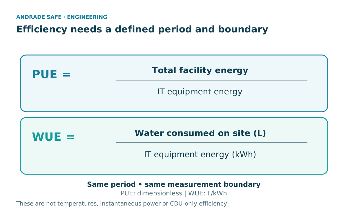
PUE is the ratio of total facility energy to energy used by IT equipment. It is dimensionless. For the comparison discussed by DOE, the energies must refer to the same boundary and period. Energy used by pumps is one part of that infrastructure, not the entire numerator.
Site WUE relates liters of water consumed on site to IT energy in kWh over the period, usually a year. The result is L/kWh. Other approaches also include water used off site to generate energy; different definitions should not be compared as though they were the same metric.
A closed liquid circuit does not mean zero total water consumption. Heat may be transferred to infrastructure using a cooling tower or another water-consuming process. Climate, heat-rejection technology, temperature limits and operating regime influence results. Direct-to-chip can improve thermal management but does not guarantee lower PUE or WUE in every scenario.
The assessment should explain where energy and water are counted. An isolated index does not show chip temperature, contingency performance or service continuity. None of these metrics has been calculated for Mumbai in this article.
Cooling Water Efficiency Opportunities for Federal Data Centers →
Best Practices Guide for Energy-Efficient Data Center Design — revised July 2024 →
| Metric | Relationship | Caution |
|---|---|---|
| PUE | Total energy / IT energy | Same boundary and period; not equivalent to pump power |
| Site WUE | Water consumed on site (L) / IT energy (kWh) | Does not automatically include water used in external energy production |
| Thermal performance | Temperatures and system response | Not demonstrated by PUE or WUE alone |
Fluid, sensors and contingency: what supports reliability
A circuit can remove 100 kW in the balance yet remain unsuitable because of unbalanced distribution, poor thermal contact, incorrect pressure or incompatible fluid quality. OCP treats the TCS as a system: wetted materials, connectors, pipes, plates, fluids and the interface with the CDU must be assessed together.
Particles, corrosion and chemical compatibility can affect channels and seals. Quality needs to be monitored over time; filtration must suit sensitive components. Microbiology may matter depending on the fluid and conditions. Introducing water or additives without checking system requirements is inappropriate.
Condensation control involves dew point and local conditions. Measuring temperature, flow, pressure and signs of leakage helps identify deviations, but each sensor needs a defined function and response. An alarm alone does not demonstrate containment or recovery. It should not be assumed that every leak automatically shuts down all racks.
Contingency, redundancy, isolation and maintenance must be coordinated with IT continuity. An operating change can affect heat, pressure and availability simultaneously. Analysis should cover prevention, detection, containment and appropriate intervention without treating this study as a procedure for working on an energized rack.
Cold Plate Cooling Loop Requirements — Rev. 2 →
Thermal Guidelines — 5th edition reference card — Table 3.1 →
Explore the balance — without turning assumptions into specifications
The lab allows you to change heat load, ΔT, specific heat capacity, density, pressure loss and overall pumping efficiency. The curve shows calculated flow using the current load and properties. The point indicates the selected ΔT; an equivalent table provides values without relying on the image.
Calculations run locally in the browser. The model does not determine fluid mixture, chip temperature, actual pressure loss, pump curve, CDU capacity, PUE or WUE. Control ranges delimit the experiment and do not represent product limits. The Python code and Portuguese HTML can be downloaded to reproduce the exercise.
Lab: coolant flow and pumping
Change the model assumptions. Calculations run in the browser; this component does not send values to external systems.
Educational model, not equipment sizing or selection. Calculated power is pumping, not chiller or whole-facility consumption.
- Mass flow (kg/s)
- 4.785
- Volumetric flow (m³/h)
- 17.277
- Flow per minute (L/min)
- 287.9
- Hydraulic power (kW)
- 0.480
- Estimated electric pumping power (kW)
- 0.800
- Provided thermal load (kW)
- 100.0
Equivalent curve table
| ΔT (K) | Flow (m³/h) |
|---|---|
| 2.00 | 43.192 |
| 3.00 | 28.795 |
| 5.00 | 17.277 |
| 8.00 | 10.798 |
| 10.00 | 8.638 |
| 15.00 | 5.759 |
Q̇ = ṁ c_p ΔT; V̇ = ṁ/ρ; P_hyd = Δp V̇; P_el = P_hyd/η_overall. kW→W: ×1,000; kPa→Pa: ×1,000; percentage efficiency: ÷100.
Steady state, single-phase liquid, constant properties and no heat loss to the surroundings. Δp is supplied, not calculated from the network. Does not determine fluid mixture, viscosity, actual losses, pump curves, branch distribution, chip temperature, CDU capacity, PUE or WUE. Ranges are lab limits, not product limits.
From heat recovery to system integration
Recovered heat may find another use when temperature, demand, distance and integration make the solution appropriate. Economization and different heat-exchange technologies can also form part of the architecture. Two-phase systems offer other possibilities with their own properties and requirements; they are not the single-phase model calculated here.
These trends do not demonstrate specific results for the Indian project. The transferable lesson is to consider energy balance, hydraulic losses and reliability together. Reducing everything to a flow rate or efficiency index leaves part of the engineering out of the analysis.
Artificial intelligence may be digital, but its limits remain physical. Each chip creates a heat-removal demand that needs a reliable path to another use or the environment. Along that route, mechanical engineering helps keep the servers running.
Frequently asked questions
What is direct-to-chip liquid cooling?
It removes heat through cold plates in thermal contact with electronic components and through liquid circulating in dedicated channels. Heat travels to other circuits and to a rejection or reuse stage. The architecture must meet equipment limits and reliability requirements. It does not automatically eliminate all air cooling in the facility.
What is the difference between a cold plate and a CDU?
The cold plate receives heat from the component through the thermal interface and transfers it to the fluid. Depending on its construction, the CDU organizes circuit distribution and control. In a liquid-to-liquid arrangement, it includes a heat-exchange boundary with the facility. Other CDU architectures exist, so functions and capacities must be checked for the product and project.
Why use water or other fluids to cool GPUs?
A compatible liquid can carry the heat load in a circuit close to components, depending on its properties and operating conditions. Pure water is not mandatory in every system. Specific heat capacity, density, viscosity, materials and equipment requirements influence selection. The thermal balance must be combined with an assessment of distribution, pumping and reliability.
How do you calculate the flow needed to remove 100 kW?
In the single-phase example, ṁ = Q̇/(c_p ΔT). With 100,000 W, 4,180 J/(kg·K) and 5 K, the result is 4.785 kg/s. Dividing by the hypothetical density of 997 kg/m³ gives approximately 17.277 m³/h or 287.9 L/min. These figures belong to the exercise; they neither specify the Mumbai circuit nor guarantee an acceptable chip temperature.
Does liquid cooling eliminate fans?
Not necessarily. Direct-to-chip can remove heat from selected components while other devices still depend on air. Heat-rejection infrastructure may also use fans. The fraction captured by liquid and the remaining solution must be determined from the equipment and architecture. There is no universal conclusion that all air disappears or has become unviable.
What does the heat exchanger inside a CDU do?
In a liquid-to-liquid architecture, it transfers heat between the TCS and FWS without normal mixing of fluids. Performance depends on conductance, temperatures, flow rates and operating conditions. The approach difference at the specified boundaries is not the ΔT through the plates. A nominal catalog capacity does not establish capacity under every condition or identify a product installed in a development.
What do ASHRAE W17, W27 and W40 mean?
In the liquid-cooling classification presented in the 2021 ASHRAE reference card, these designations refer to the maximum facility water supply temperature associated with the equipment class: 17, 27 or 40 °C, respectively. They are not chip temperatures or universally ideal values. They must be interpreted alongside actual equipment conditions and requirements.
Does the system use less water than air cooling?
The technology’s name alone does not establish this. A closed technology circuit may transfer heat to external infrastructure that consumes water. Site WUE depends on the volume counted, IT energy, climate and architecture. Comparisons require the same boundaries and periods; indices from other developments do not demonstrate performance in the Mumbai case.
What happens if coolant leaks?
The response depends on the architecture and contingency plan. Prevention, detection, containment, isolation and intervention must be coordinated with circuit and IT conditions. It should not be assumed that every sensor triggers an automatic shutdown of all racks. This study does not provide a procedure for energized intervention or recovery of a real facility.
What does the 30 MW announcement in Mumbai mean?
The October 2026 announcement describes announced AI computing capacity supported by the SFN solution. It does not present a measurement of 30 MW removed by liquid or define the rating of a single CDU. Actual models, flow rates, temperatures and metrics cannot be deduced from that figure. Our 100 kW exercise is independent and hypothetical.
References
- Vertiv deployment announcement reproduced by Express ComputerExpress Computer
- Vertiv disclosure reproduced by WebnewswireWebnewswire
- CapitaLand India Trust — 1H2026 release; July handoverCapitaLand
- CLDC Mumbai 01 — FactsheetCapitaLand
- Cold Plate Cooling Loop Requirements — Rev. 2Open Compute Project
- ACS Liquid Cooling Cold Plate Requirements — Rev. 1.0Open Compute Project
- Cooling Water Efficiency Opportunities for Federal Data CentersDOE / FEMP
- Best Practices Guide for Energy-Efficient Data Center Design — revised July 2024DOE / NREL
- Thermal Guidelines — 5th edition reference card — Table 3.1ASHRAE
- CoolChip CDU — liquid-to-liquid and liquid-to-air architectureVertiv