
Understand safety light curtains, OSSD outputs and the conceptual separation-distance calculation described for ISO 13855:2024.
Detecting a hand is only the beginning
A machine can have a modern light curtain and remain dangerous if the operator’s hand reaches the tool before the movement ends. The curtain is the first link in a chain: it identifies interruption of the field, changes safety-related signals and depends on the response of the control system and machine. In Component Study 03, we examine why milliseconds and millimetres matter so much.
The previous studies followed the safety PLC and final hydraulic elements. We now trace the chain in the opposite direction, starting with optical detection. The diagrams and exercise are generic; no parameter represents a real installation. A curtain does not support a load, contain ejected material or establish, on its own, that residual energy is absent.
Emitter, receiver and optical field
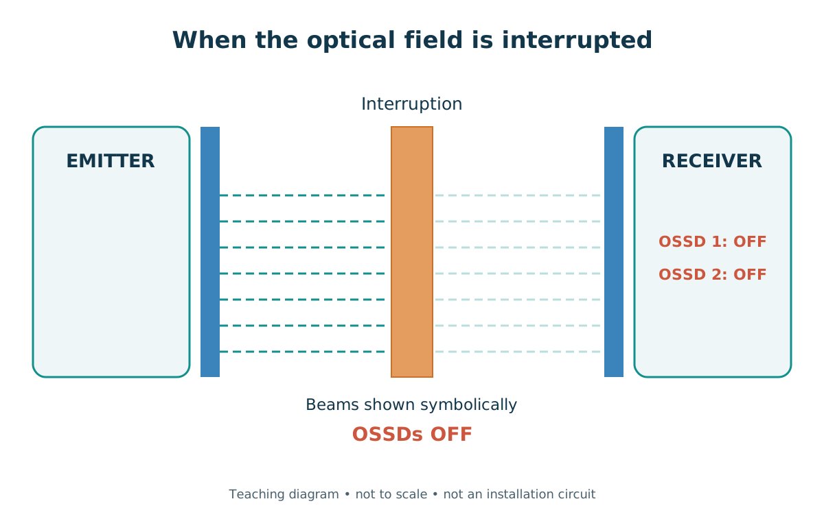
A light curtain uses an emitter and a receiver to monitor a field through photoelectric beams, usually infrared. The equipment evaluates reception according to its construction and diagnostics. When an object with detectable characteristics interrupts the relevant field, the outputs enter the state specified to request the protective function. Response time is finite: detection and signalling are not instantaneous.
AOPD stands for active opto-electronic protective device. ESPE stands for electro-sensitive protective equipment. IEC 61496-1:2020 addresses general requirements for ESPE; Part 2:2020 addresses particular requirements for equipment using AOPDs. These references concern the device and its interface; they do not determine its position in front of every possible hazard.
The number of lines drawn in the figure is illustrative. It does not represent a product’s beam count, resolution or pin assignment. Detection must be assessed within the field actually protected, considering the declared characteristics, installation, integration and hazards present. An object outside that field does not become detectable merely because a curtain is nearby.
Resolution, height, range and separation: four concepts
Detection capability, also called nominal resolution, characterises what the device can detect under the declared conditions. Values such as 14 mm and 30 mm belong to specific models. They do not mean that every smaller object, every hand position or every installation condition will always be detected. Resolution is also not the distance between the curtain and the tool.
Protective-field height is the protected extent along the profiles. Optical range is the operating distance between emitter and receiver. Separation distance is the positioning relative to the hazardous zone, selected using the applicable method. Confusing these quantities can lead to equipment with a suitable field and range being installed where it cannot protect an approach to the hazard.
As a documented example, the SICK datasheet for deTec4 Core C4C-PA06030A10000, part number 1063377, issued in July 2026, specifies 30 mm resolution, 600 mm protective-field height, 15 m range and two PNP OSSD outputs. These are data for that specific reference, not specifications for every curtain. The 20 ms used in this article’s exercise were not taken from that datasheet.
Reflections, alignment, dirt, interference between fields and unprotected zones must be assessed using the manual and the design. Features that change detection, such as blanking or reduced resolution, can also change effective capability and protective conditions. Selecting a nominal resolution from a catalogue is not enough to consider the assessment complete.
SICK — deTec4 Core C4C-PA06030A10000 / 1063377 — datasheet 2026-07-25 →
| Quantity | What it describes | What it does not establish |
|---|---|---|
| Detection capability | Detectable dimension under the declared conditions | Universal detection of every object |
| Field height | Extent of the protected region | Absence of access over or under it |
| Optical range | Permitted distance between emitter and receiver | Distance to the hazard |
| Separation | Positioning relative to the hazardous zone | Load holding or containment of ejected materials |
OSSD1 and OSSD2: two signals that must be interpreted
OSSD stands for output signal switching device. In devices with two safety-related outputs, OSSD1 and OSSD2 provide information that a compatible relay or controller must evaluate. In the field-interruption example described by SICK, both switch to OFF. This requests a response from the chain; it does not establish that physical movement has already ended.
It is incorrect to claim that every fault always places both outputs in OFF simultaneously. The consulted datasheet defines the safe state in the event of a fault as at least one OSSD being OFF. Joint evaluation and diagnostics are part of integration. Cross-circuits between channels, incompatible states and relevant faults can cause lockout, depending on the equipment and its configuration.
Electronic OSSDs can include brief test pulses. The connected interface must be compatible with the documented behaviour, without indiscriminately treating these pulses as a conventional command. A signalling output or an indicator in the process PLC does not replace safe evaluation of the channels. No connection timing, terminal assignments or implementation wiring diagrams are provided here.
Two outputs also do not establish the PL achieved by the complete function. Type 4 equipment, classified under the relevant ESPE requirements, can be integrated into applications up to PL e under appropriate conditions. Type 4 and PL e are not equivalent names: the function’s level depends on subsystems, architecture, application and validation.
SICK — deTec4 Core C4C-PA06030A10000 / 1063377 — datasheet 2026-07-25 →
From an interrupted field to the end of the hazard
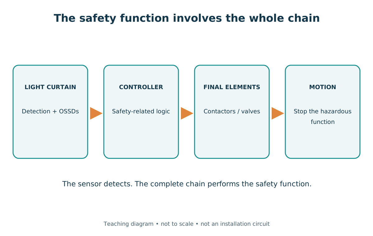
The functional path starts with detection, continues through the OSSDs and safety-related logic, and reaches the final elements. Contactors, drives or valves produce the response that acts on the machine. Only then is the end of hazardous movement, or another defined safe state, assessed. The figure shows responsibilities, not a circuit ready to assemble.
Removing an electrical command can precede mechanical stopping. Detection, processing and actuation introduce delays, alongside machine dynamics. Inertia, gravity and stored pressure do not disappear because an output changes state. The function must control the hazard and demonstrate its response under the specified conditions.
This connects with the hydraulic study: detecting an approach does not retain a suspended tool. Load holding and treatment of residual energy require their own functions and measures. Likewise, a curtain does not contain chips, hot fluids or other ejected materials. The separation method is not, by itself, protection against these hazards.
Reset, EDM and prevention of restart
Reset restores the possibility of accepting a new command; it must not be confused with automatic starting. The application must define whether the restart interlock is in the device, external logic or another appropriate part of the function. The consulted miniTwin2 manual, dated May 2024, distinguishes resetting the OSSDs from the subsequent start command.
EDM, external device monitoring, monitors feedback from external elements where applicable to the architecture. In a hypothetical example, a contactor does not return to its expected state after an interruption. The logic identifies the inconsistency and prevents the intended recovery. Contact feedback is not universal proof that movement, pressure or energy is absent.
Reset position, visibility of the zone and access by people must be included in the analysis. If someone passes through the field and remains behind it, the beams can become clear without establishing that the hazardous zone is empty. Restart prevention and other protections must address this situation; a curtain is not a presence detector for every point behind the optical plane.
Response time and distance cannot be separated
A person can continue approaching while the chain responds and the machine stops. A positioning method therefore relates total time to an approach parameter and allowances for reach and application. A short sensor response time does not automatically compensate for a long or variable mechanical stopping time.
The time used in the design must have a clear origin and scope. It can involve declared component times, appropriate measurements and factors required by the method. If a measurement already covers the complete interval from interruption to the end of the hazard, portions it includes must not be added again. Breaking down an example does not justify double-counting real times.
Stop-time variation, changes in braking, load and measurement uncertainty must be considered. A real assessment requires instruments, suitable test conditions and an appropriate procedure conducted by a competent team. The laboratory below measures nothing: its values are entered or selected by the reader and do not represent a machine test.
ISO 13855:2024 and NR-12: documents that must be distinguished
The official catalogue confirms ISO 13855:2024 as the third edition, published in November 2024, replacing the 2010 edition. The publication concerns the positioning of safeguards relative to human approach. Pilz’s technical presentation describes S = K × T + D_DS + Z for the static situation considered.
S is separation distance in mm. K is the approach-speed parameter in mm/s. T is the total time relevant to the method, in seconds. D_DS represents the greatest applicable reach allowance among the cases assessed, and Z represents application-specific factors, both in mm. These terms are not numbers freely selected to reduce a distance.
The assessment involves approach direction, reaching over, through or under, hazardous-zone geometry, field height and the possibility of passing through. Pilz’s presentation also distinguishes dynamic cases that can include S_M, associated with movement of the hazardous zone. The static expression is not a universal solution for every movement or access path.
In Brazil, the official NR-12 text provided by the Ministry of Labour and Employment and consulted on October 11, 2026, retains S = K × T + C in Annex I. The annex contains a table of C values associated with detection capability and other conditions. Publication of the international 2024 edition does not justify stating that the Brazilian regulatory text was automatically rewritten or that the two presentations are equivalent.
The relationship C = 8 × (d − 14) appears, for example, in the SICK mac4 manual dated April 2016 for an orthogonal-approach treatment subject to its own conditions. It is not the universal rule for the table in NR-12 Annex I, nor should it be inserted as though it represented all of D_DS + Z in the 2024 edition. This article’s example does not calculate C from resolution.
The public sources consulted are the ISO catalogue, the federal text and the manufacturer’s technical presentation. The copyrighted ISO standard was not consulted in full. This explanation does not determine legal precedence between documents or replace checking the method and editions applicable to a project.
ISO — ISO 13855:2024 — edition 3 / 2024-11 →
Pilz — EN ISO 13855 — positioning of safeguards →
Ministério do Trabalho e Emprego — NR-12 — texto oficial consultado em 11/10/2026 →
SICK — mac4 — 8014264/YUP1/2016-04-06 (historical example) →
| Presentation | Expression cited | Essential consideration |
|---|---|---|
| Pilz on ISO 13855:2024, static case | S = K × T + D_DS + Z | Determine reach, factors and conditions; dynamic cases can differ |
| Consulted NR-12 Annex I | S = K × T + C | Examine the table and conditions in the Brazilian text |
| mac4 example, 2016 manual | C = 8 × (d − 14) | Historical orthogonal-approach treatment; does not replace current terms |
Worked exercise: 300 ms and fictitious allowances
Imagine a hypothetical vertical light curtain. To illustrate time composition, we assume 20 ms for sensor response, 15 ms for safety logic, 240 ms for the machine response until the hazard ends, and an additional educational tolerance of 25 ms. These are invented data unrelated to any product or installation: T = 300 ms = 0.300 s.
We assume K = 2,000 mm/s, D_DS = 120 mm and Z = 50 mm solely to explore the equation. Both allowances are fictitious, as if they had already been determined using the appropriate method. They are not tabulated values for 30 mm resolution or universal margins. Thus, S_illustrative = 2,000 × 0.300 + 120 + 50 = 770 mm.
Pilz describes conditions under which, after a calculation with K = 2,000 mm/s yields more than 500 mm, recalculation with 1,600 mm/s can be considered while observing the method’s criteria and the 500 mm lower limit. This is not a free selection to obtain a smaller result. Using the same fictitious numbers, the second mathematical scenario gives 650 mm; this does not approve an installation distance.
If the mechanical portion increases from 240 to 350 ms, the total becomes 410 ms. With K = 2,000 mm/s and the same allowances, the result becomes 990 mm: an additional 110 ms corresponds to 220 mm in the K × T term. The example demonstrates sensitivity; it does not define permissible wear, a validated distance or a release condition.
Pilz — EN ISO 13855 — positioning of safeguards →
| Portion or scenario | Assumption | Result |
|---|---|---|
| Sensor response | 20 ms | Assumption, not deTec4 Core data |
| Safety logic | 15 ms | Educational assumption |
| Mechanical response | 240 ms | Assumption until the hazard ends |
| Additional tolerance | 25 ms | Not a universal margin |
| Total time | 20 + 15 + 240 + 25 | 300 ms = 0.300 s |
| K = 2,000 scenario | 600 + 120 + 50 | Illustrative 770 mm |
| K = 1,600 scenario | 480 + 120 + 50 | Illustrative 650 mm; conditional use of K |
| Mechanical response of 350 ms | T = 0.410 s; K = 2,000 | Illustrative 990 mm |

Detection is not containment: the curtain’s limits
Selecting a light curtain must account for hazards beyond approach to the optical plane. Detection and command removal may be necessary, but they do not replace load holding, containment or complementary protection. The distance method also does not, on its own, eliminate the risk of remaining undetected in a zone.
Muting, blanking and reduced resolution are specific functions of particular equipment. They can temporarily change protective action or effective detection capability under the designed conditions. The application requires analysis, appropriate measures and validation; this article does not provide configurations, protective-function defeat or bypass procedures.
ISO — ISO 13855:2024 — edition 3 / 2024-11 →
SICK — mac4 — 8014264/YUP1/2016-04-06 (historical example) →
SICK — deTec4 HG — 8023856/1SWC/2026-02-05 →
| Situation | Curtain limitation | What to consider |
|---|---|---|
| Chips, particles, hot fluids | An optical field is not a physical barrier | Containment and protection appropriate to the hazard |
| Load that can fall | OSSD OFF does not support mass | Load holding and final-element architecture |
| Person remains behind the field | A clear field does not establish an empty zone | Geometry, detection and restart prevention |
| Reflections or interference | Can compromise detection | Manual, alignment and optical conditions |
| Functions that change detection | Can change effective capability | Model requirements and application validation |
| Long or inconsistent stopping | Command removed does not mean stopping is complete | Total time, variation and uncertainties |
Laboratory: explore states and the mathematical sum
Interrupt the field to see both illustrated OSSDs in OFF. Then clear it: in this model, the sensor returns to ON, but an illustrative external reset remains separate from starting. The laboratory represents a conceptual integration option; the behaviour of an actual product depends on its configuration. There is no button to command a machine.
Change the times and allowances to follow the composition of T and S. Choosing K displays only two arithmetic scenarios; the form does not assess whether recalculation is permitted. D_DS and Z remain arbitrarily entered data. The graphical bar has an equivalent table for reading the values.
This simulation is educational and uncertified. It does not implement ISO 13855 in full, calculate PL/SIL, measure stopping, or determine height, range, geometry, reflections, alternative access paths or dynamic factors. It does not connect to a controller, machine or industrial network. The Portuguese HTML is also available for local study.
Lab: detection and illustrative separation
Educational, uncertified simulation. It does not determine a compliant distance or authorize installation.
Conceptual optical field
OSSD1: ON (model) · OSSD2: ON (model)
A clear field does not prove an empty zone. Illustrative reset is pending; starting is not authorized.
This model represents automatic sensor-output recovery and a separate reset in external logic. Actual behavior depends on the equipment and configuration.
Mathematical composition — not a design calculation
Choosing 1,600 only compares arithmetic. This lab does not check recalculation eligibility, distance minimums or the normative selection of K.
- Illustrative total T
- 0.300 s
- K × T contribution
- 600.0 mm
- Illustrative arithmetic S
- 770.0 mm
S ≈ 2,000 × 0.300000 + 120.000 + 50.000 ≈ 770.0 mm
| Contribution | Value (mm) |
|---|---|
| K × T | 600.0 |
| D_DS | 120.0 |
| Z | 50.0 |
Times and supplements are fictitious. Ranges define this lab, not a product. It does not assess reach, geometry, height, reflections, alternative access, S_M, residual energy, PL/SIL or actual stopping. No result is technical approval.
Distance begins with understanding the function
The curtain detects a condition within its field; the OSSDs carry that information to the chain; the logic and final elements must produce a verifiable physical response. This integration makes it possible to assess protection, with defined requirements and known limits.
A light curtain does not make a machine safe merely by being installed. It fulfils its role only when detection occurs in time and the rest of the machine responds safely and verifiably. Safety distance begins where the belief that detection alone is sufficient ends.
Frequently asked questions
What is a safety light curtain used for?
It monitors an optical field and provides safety-related signals when a detectable interruption or another device-defined condition occurs. Its effectiveness depends on integration with the logic, final elements and machine response. It is not a physical barrier against ejected materials or a load-supporting device. Positioning, access and fault behaviour must be assessed.
What are OSSD1 and OSSD2?
They are two safety-related outputs that a compatible interface must evaluate along with the equipment’s diagnostics. In the interrupted-field example, both switch to OFF. It must not be generalised that every fault always produces exactly the same state on both. Test pulses, faults and lockouts depend on the product’s documentation and configuration.
Does Type 4 mean the same thing as PL e?
No. Type 4 belongs to the classification of electro-sensitive protective equipment under the applicable requirements. PL characterises the performance of the safety-related function. A Type 4 device can be integrated into applications up to PL e under appropriate conditions, but the level achieved by the chain depends on its subsystems, architecture, use and validation.
How does 14 or 30 mm resolution affect detection?
Nominal capability describes what the model detects under conditions declared by the manufacturer. It is not field height, range between profiles or distance to the tool. Geometry, installation and functions such as reduced resolution can change the assessment. These values do not guarantee detection of every smaller object or every hand position.
How is a machine’s stopping time measured?
A real assessment requires suitable instruments, methods and conditions under an authorised procedure with a competent team. The measured interval must be defined, variation and uncertainties considered, and portions already included in a total measurement must not be added again. The laboratory does not measure stopping: all times are educational assumptions, with no test validity.
Which formula is used with ISO 13855:2024?
Pilz’s presentation shows S = K × T + D_DS + Z for the static situation considered. The complete method requires defining reach, approach, geometry and applicable factors; dynamic cases can include other terms. Completing the expression does not establish a valid design. Consult the standard and requirements relevant to the application before determining positioning.
Can I use S = K × T + C from NR-12 without other checks?
No. Annex I includes conditions, a table for C and references that must be examined alongside the machine and other requirements. The expression must not be confused with the 2024 presentation or any historical formula from a manual. This article distinguishes their origins without giving a legal opinion on precedence between normative documents.
What if someone passes through and stays behind the curtain?
The optical plane can become clear after passage without establishing that the hazardous region is empty. The design must address this situation, considering geometry, complementary protections, restart prevention and appropriate detection where needed. Clearing the field must not automatically be interpreted as authorisation to start movement.
Does a curtain prevent loads falling or particles being ejected?
Not by itself. Detection and command removal do not support a mass or contain ejected material. Gravitational loads, residual pressure, chips, hot fluids and other hazards require suitable functions and measures. The separation method does not replace load holding or containment. The chain must be assessed against the hazards actually present.
Why must reset not automatically start the machine?
Reset restores a condition for accepting a new command; it does not establish that starting movement at that instant is safe. Restart prevention must account for people, visibility, access and remaining hazards. Integration can place an interlock in the device or external logic, according to the design. In the laboratory, reset produces no machine command.
References
- ISO 13855:2024 — edition 3 / 2024-11ISO
- EN ISO 13855 — positioning of safeguardsPilz
- IEC 61496-1:2020 — General requirements and testsIEC
- IEC 61496-2:2020 — AOPD requirementsIEC
- deTec4 Core C4C-PA06030A10000 / 1063377 — datasheet 2026-07-25SICK
- miniTwin2 — 8013482/1IZ4/2024-05-07SICK
- NR-12 — texto oficial consultado em 11/10/2026Ministério do Trabalho e Emprego
- mac4 — 8014264/YUP1/2016-04-06 (historical example)SICK
- deTec4 — 8021645/1SWC/2026-02-04SICK
- deTec4 HG — 8023856/1SWC/2026-02-05SICK
- ISO 13849-1:2023ISO
- EN/IEC 61496 — ESPE types and performancePilz